
1. Introduction
The ALINX AL321 Platform Cable USB Blaster is a versatile programming tool designed for Xilinx FPGA devices. It facilitates JTAG programming and debugging, supporting a wide range of Xilinx software versions and operating systems. This manual provides essential information for setting up, operating, and maintaining your AL321 USB Blaster.
2. Package Contents
Please verify that all items listed below are included in your package:
- 1 x ALINX AL321 USB Blaster Unit
- 1 x 10-Core 2.54mm Pitch Cable
- 1 x USB Type-A to Mini-B Cable

Image 2.1: ALINX AL321 USB Blaster and included cables. The image displays the red USB Blaster unit, a flat gray 10-core ribbon cable, and a red USB cable.
3. Features
- Supports Xilinx ISE versions 9.1 to 14.7.
- Compatible with all versions of Xilinx Vivado software.
- Supports Impact and Chipscope for debugging and programming.
- Compatible with Windows and Linux operating systems.
- Automatically detects and adapts to target I/O voltage levels.
- Supports devices using 5V (TTL), 3.3V (LVCMOS), 2.5V, 1.8V, and 1.5V interface levels.
- Features an LED status indicator for operational feedback.
- Capable of device programming for SPI interface flash PROM.
4. System Requirements
- Operating System: Windows (XP/7/8/10) or Linux.
- Software: Xilinx ISE (9.1-14.7) or Xilinx Vivado (all versions).
- Available USB Port.
5. Setup
Follow these steps to set up your ALINX AL321 USB Blaster:
- Connect to Computer: Connect the USB Type-A end of the provided USB cable to an available USB port on your computer and the Mini-B end to the AL321 USB Blaster unit. The status LED on the blaster should illuminate, indicating power.
- Driver Installation: Upon first connection, your operating system may attempt to install drivers automatically. If not, drivers are typically included with your Xilinx ISE or Vivado software installation. Refer to your Xilinx software documentation for specific driver installation instructions.
- Connect to Target Device: Use the 10-Core 2.54mm Pitch Cable to connect the AL321 USB Blaster to the JTAG header on your Xilinx FPGA development board. Ensure correct pin orientation.
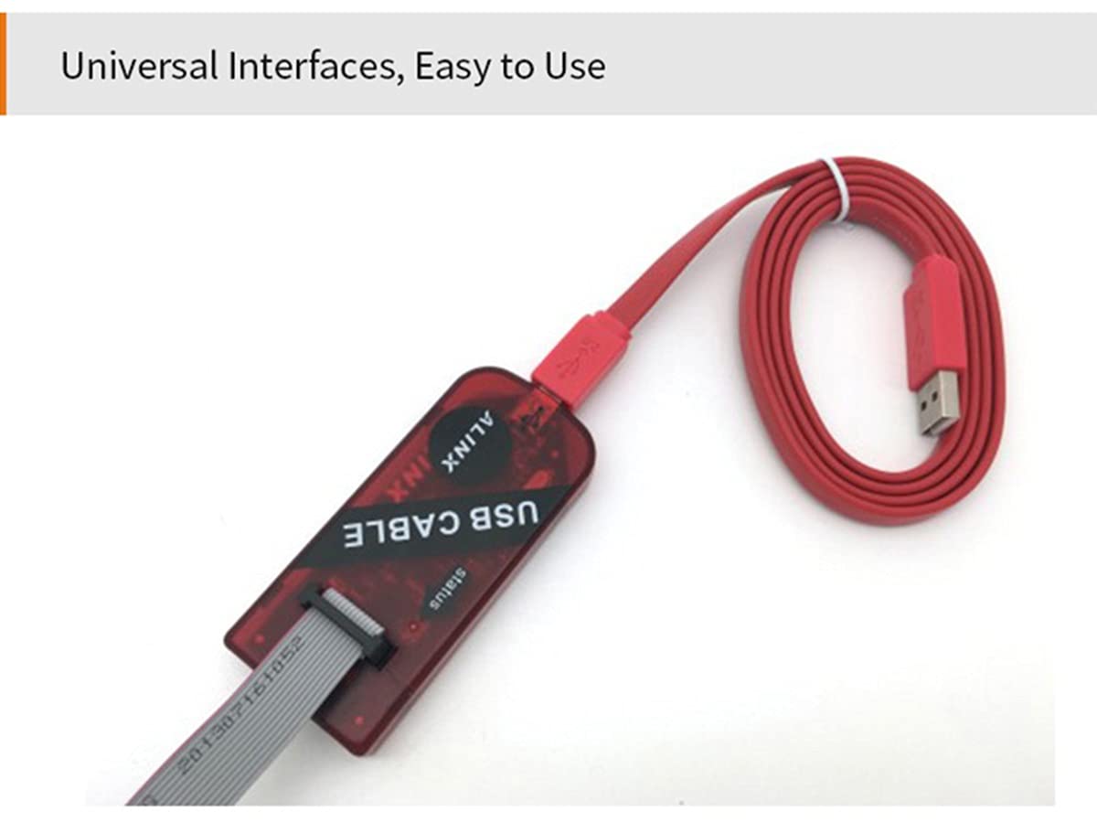
Image 5.1: ALINX AL321 USB Blaster with USB and JTAG cables connected. The image shows the red blaster unit with a red USB cable plugged into one end and a gray 10-core ribbon cable connected to the JTAG interface.
6. Operating Instructions
6.1 Pin Definition
Understanding the pinout is crucial for correct connection to your target FPGA board. Pin 1 is typically indicated on the device.

Image 6.1: Close-up of the ALINX AL321 USB Blaster showing the location of Pin 1 on the JTAG header, accompanied by a schematic diagram detailing the JTAG signal assignments (TMS, TCK, TDI, TDO) and voltage reference (VREF).
6.2 Interface Types
The AL321 USB Blaster supports two common JTAG interface spacings without requiring external conversion:
- 2.54mm Spacing 10 Pin Interface: This is a standard interface for many FPGA boards.
- 2.0mm Spacing 14 Pin Interface: This interface provides additional pins, often for ground or other signals.
The device automatically adapts to the target I/O voltage, simplifying connection.

Image 6.2: The ALINX AL321 USB Blaster demonstrating its compatibility with both 2.54mm 10-pin and 2.0mm 14-pin JTAG interfaces. The image shows close-ups of the blaster's header with a 10-pin connector and a 14-pin connector, along with a table defining the pin assignments for TDI, TMS, TDO, TCK, VREF, and GND.
6.3 Software Usage
Once connected and drivers are installed, open your Xilinx ISE or Vivado software. The AL321 USB Blaster should be detected as a programming cable. You can then use the software's programming tools (e.g., Impact for ISE, Hardware Manager for Vivado) to download bitstreams, program flash memory, or perform JTAG debugging on your FPGA device.
7. Specifications
- Model: AL321
- Supported Software: Xilinx ISE (9.1-14.7), Xilinx Vivado (all versions), Impact, Chipscope
- Supported Operating Systems: Windows, Linux
- Supported I/O Voltage Levels: 5V (TTL), 3.3V (LVCMOS), 2.5V, 1.8V, 1.5V
- Interface: JTAG, SPI flash PROM programming
- Connectivity: USB 2.0
8. Troubleshooting
If you encounter issues, consider the following:
- Device Not Detected: Ensure the USB cable is securely connected to both the computer and the AL321. Verify that the status LED on the blaster is on. Reinstall or update USB drivers if necessary.
- Programming Errors: Check the connection between the AL321 and the target FPGA board. Ensure the JTAG cable is correctly oriented and all pins are making good contact. Verify that the target FPGA board is powered on and configured correctly.
- Software Issues: Confirm that your Xilinx software (ISE or Vivado) is correctly installed and configured to recognize the AL321 programmer. Refer to Xilinx documentation for specific software setup.
- Voltage Mismatch: The AL321 automatically adapts to target I/O voltage. However, ensure your target board's voltage is within the supported range (1.5V to 5V).
9. Maintenance
To ensure the longevity and reliable operation of your ALINX AL321 USB Blaster:
- Keep the device clean and free from dust and debris. Use a soft, dry cloth for cleaning.
- Store the device in a cool, dry place away from direct sunlight and extreme temperatures.
- Avoid exposing the device to moisture or corrosive substances.
- Handle cables and connectors gently to prevent damage.
10. Warranty and Support
For information regarding warranty coverage, technical support, or service for your ALINX AL321 USB Blaster, please refer to the documentation provided at the time of purchase or visit the official ALINX website. Keep your purchase receipt as proof of purchase for warranty claims.