1. Product Overview
The Custom Connector QC08 is an 8-pin relay socket designed for use with Double Pole Double Throw (DPDT) relays. It features binder head screws for secure wire connections and is engineered for base mounting applications. This manual provides essential information for the proper installation, operation, and maintenance of your QC08 relay socket.
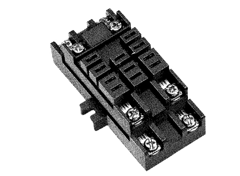
Figure 1: Custom Connector QC08 8-Pin DPDT Relay Socket. This image displays the top-down view of the black relay socket, highlighting its eight binder head screw terminals and the base mount design.
2. Setup and Installation
Proper installation ensures reliable operation of the QC08 relay socket. Follow these steps carefully:
- Mounting: The QC08 is designed for base mounting. Secure the socket to a stable surface using appropriate fasteners through the designated mounting holes. Ensure the mounting surface is clean and free from conductive debris.
- Wiring:
- Identify the correct wiring diagram for your specific DPDT relay. Refer to the relay's manufacturer specifications.
- Prepare the wire ends by stripping approximately 6-8mm (0.25-0.3 inches) of insulation.
- Loosen the binder head screws on the terminals.
- Insert the stripped wire ends into the corresponding terminals. Ensure no stray wire strands are present that could cause short circuits.
- Tighten the binder head screws firmly to secure the wires. Do not overtighten, as this can damage the terminals or wires.
- Verify all connections are secure and correctly wired according to your relay's specifications.
- Relay Insertion: Carefully align the pins of the DPDT relay with the corresponding receptacles in the QC08 socket. Gently press the relay into the socket until it is fully seated. Do not force the relay, as this can bend pins or damage the socket.
Safety Note: Always disconnect power to the circuit before performing any installation or wiring to prevent electrical shock.
3. Operating Instructions
Once the QC08 relay socket and relay are correctly installed and wired, operation is straightforward:
- Power Connection: Apply power to the control circuit connected to the relay coil terminals.
- Relay Activation: When the control signal is applied to the relay coil, the relay will activate, changing the state of its DPDT contacts.
- Load Operation: The connected load(s) will operate according to the switched state of the relay contacts.
The DPDT (Double Pole Double Throw) configuration allows for switching two separate circuits, each with two possible states (normally open and normally closed). Ensure your application's wiring correctly utilizes this configuration.
4. Maintenance
The Custom Connector QC08 relay socket requires minimal maintenance to ensure long-term reliable performance.
- Regular Inspection: Periodically inspect the socket and wiring for any signs of damage, loose connections, or corrosion.
- Cleaning: If necessary, gently clean the exterior of the socket with a dry, soft cloth. Avoid using harsh chemicals or abrasive materials. Ensure no debris accumulates within the terminal areas.
- Connection Integrity: Re-tighten binder head screws if any looseness is detected, ensuring wires remain securely fastened.
Caution: Always disconnect power before performing any maintenance or inspection.
5. Troubleshooting
If you encounter issues with your QC08 relay socket, consider the following common troubleshooting steps:
- No Relay Activation:
- Verify that power is correctly supplied to the relay coil terminals.
- Check for loose or incorrect wiring connections at the binder head screws.
- Ensure the relay is fully and correctly seated in the socket.
- Test the relay itself (if possible) to rule out a faulty relay.
- Intermittent Operation:
- Inspect all wire connections for looseness or corrosion.
- Check for any physical damage to the socket or relay pins.
- Overheating:
- Ensure the relay and socket are operating within their specified current and voltage ratings.
- Verify that wire gauges are appropriate for the current load.
- Check for short circuits or excessive load.
If problems persist after following these steps, contact Custom Connector support for further assistance.
6. Specifications
| Model | QC08 |
| Number of Pins | 8 |
| Contact Configuration | DPDT (Double Pole Double Throw) |
| Terminal Type | Binder Head Screws |
| Mounting | Base Mount |
| Manufacturer | Custom Connector |
| ASIN | B08NT521H6 |
| Date First Available | November 18, 2020 |
7. Warranty and Support
For warranty information or technical support regarding your Custom Connector QC08 relay socket, please contact Custom Connector directly. Details regarding specific warranty periods and terms are typically provided with the product packaging or can be obtained from the manufacturer's official website.
Contact Information:
- Manufacturer: Custom Connector
- Refer to the official Custom Connector website for the most current contact details, including phone numbers and email addresses for technical support.


