1. Introduction to GFCI Outlets
A Ground Fault Circuit Interrupter (GFCI) outlet is a fast-acting circuit breaker designed to shut off electric power in the event of a ground fault within as little as 1/40 of a second. It is designed to protect people from severe or fatal electric shocks. This ANKO GFCI outlet features self-testing capabilities, an LED indicator, and is tamper-resistant and weather-resistant for both indoor and outdoor applications.

Image 1.1: Four ANKO GFCI 20 Amp Outlets. These outlets are designed for safety, featuring test and reset buttons and an LED indicator for status.

Image 1.2: Key features of the ANKO GFCI outlet, including UL listing, tamper and weather resistance, self-test function, and wiring options.
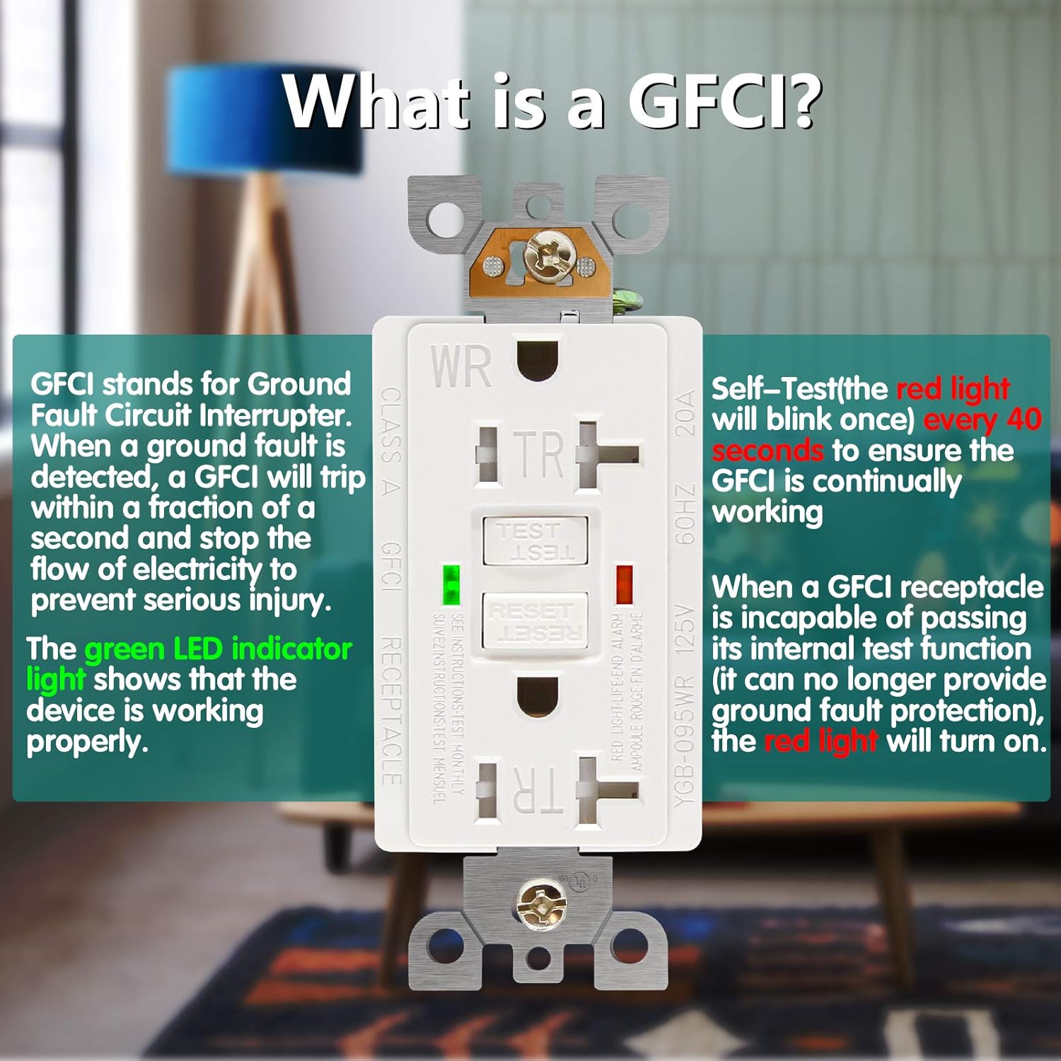
Image 1.3: Explanation of GFCI functionality, illustrating how it protects against ground faults and the meaning of its LED indicators.
2. What's in the Box
Your ANKO GFCI Outlet package includes the following components:
- GFCI Outlet (20 Amp)
- Decorator Wall Plate
- Mounting Screws
- Complete Installation Instructions (this manual)
3. Important Safety Information
Please read and understand all instructions before installing or using this product. Failure to follow these instructions may result in electric shock, fire, or serious injury.
- WARNING: Turn off power at the circuit breaker or fuse box before wiring.
- Installation should be performed by a qualified electrician or a knowledgeable individual familiar with electrical wiring.
- Do not use this device with aluminum wiring. Use only with copper or copper-clad wire.
- Ensure all wire connections are secure and properly insulated.
- This GFCI is designed for 20 Amp, 125 Volt, 60HZ circuits. Do not exceed these ratings.
- The tamper-resistant feature helps prevent accidental insertion of foreign objects into the receptacle openings, enhancing child safety.
- The weather-resistant feature provides enhanced protection against moisture and UV degradation, making it suitable for damp or wet locations.
4. Product Specifications
| Feature | Specification |
|---|---|
| Model Number | ANKPS-301-4P |
| Electrical Rating | 20 Amp, 125 Volt, 60 Hz |
| Product Dimensions | 4.2 x 1.8 x 1.6 inches (Outlet) |
| Wall Plate Dimensions | 4.6"L x 2.7"W |
| Weight | 1.48 Pounds (per 4-pack) |
| Material | High-impact resistant thermoplastic, Plastic, Stainless Steel |
| Certifications | UL Listed (YGB-095WR) |
| Features | Self-Test, LED Indicator, Tamper-Resistant, Weather-Resistant |
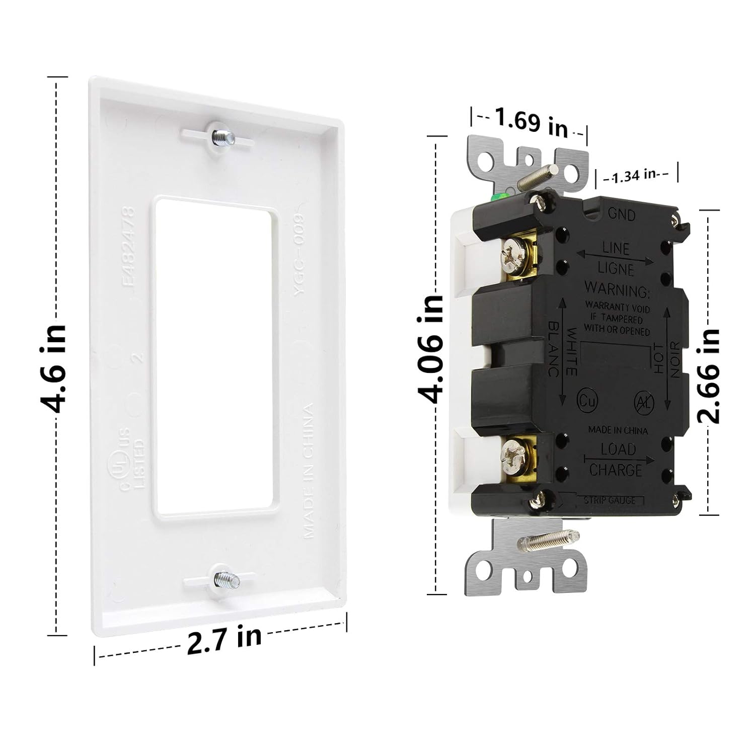
Image 4.1: Dimensions of the ANKO GFCI outlet and its accompanying decorator wall plate.
5. Installation Guide
Follow these steps carefully to install your ANKO GFCI outlet. Installation typically takes about 10 minutes.
5.1. Preparation
- IMPORTANT: Turn off power to the circuit at the main service panel (circuit breaker or fuse box) before beginning work. Verify power is off using a voltage tester.
- Remove the existing wall plate and outlet from the electrical box.
- Carefully pull the wires out of the electrical box.
5.2. Wiring Connections
Identify the wires in your electrical box:
- LINE Wires: These wires bring power from the circuit breaker. Typically, the black wire is the Hot (LINE Hot) and the white wire is the Neutral (LINE White).
- LOAD Wires: These wires carry power to downstream outlets or devices protected by this GFCI. Typically, the black wire is the Hot (LOAD Hot) and the white wire is the Neutral (LOAD White).
- GROUND Wire: This is typically a bare copper or green insulated wire.
The ANKO GFCI outlet supports both back-wire and side-wire connections. For side-wire connections, strip wires approximately 1 inch (2.5 cm) and wrap 2/3 of the way around the screw.

Image 5.1: Terminal identification on the ANKO GFCI outlet for proper wiring.
5.3. Wiring Scenarios
Scenario A: One Cable (2-3 Wires) Entering the Box
This scenario is common when the GFCI is at the end of a circuit or is the only outlet on a branch.
- Connect the LINE Hot (black) wire from the electrical box to the LINE Hot Terminal (brass screw) on the GFCI.
- Connect the LINE Neutral (white) wire from the electrical box to the LINE White Terminal (silver screw) on the GFCI.
- Connect the Ground (bare copper or green) wire from the electrical box to the Grounding Terminal (green screw) on the GFCI. If the box has a grounding terminal, connect the ground wire from the cable to it, then run a pigtail to the GFCI's grounding terminal.
- Cap off or insulate the LOAD terminals on the GFCI. Do not connect any wires to the LOAD terminals in this scenario.
Scenario B: Two Cables (4-6 Wires) Entering the Box
This scenario is used when the GFCI will protect other downstream outlets or devices.
- Connect the incoming LINE Hot (black) wire to the LINE Hot Terminal (brass screw) on the GFCI.
- Connect the incoming LINE Neutral (white) wire to the LINE White Terminal (silver screw) on the GFCI.
- Connect the outgoing LOAD Hot (black) wire to the LOAD Hot Terminal (brass screw, typically covered by yellow tape) on the GFCI.
- Connect the outgoing LOAD Neutral (white) wire to the LOAD White Terminal (silver screw, typically covered by yellow tape) on the GFCI.
- Connect all Ground wires (bare copper or green) together with a wire connector, then run a pigtail to the Grounding Terminal (green screw) on the GFCI. If the box has a grounding terminal, connect the ground wires from the cables to it, then run a pigtail to the GFCI's grounding terminal.

Image 5.2: Detailed wiring diagrams for common installation scenarios: single cable and dual cable connections.
5.4. Final Steps
- Carefully push the wired GFCI outlet back into the electrical box.
- Secure the GFCI to the electrical box using the provided mounting screws.
- Attach the decorator wall plate using the provided screws.
- Restore power at the main service panel.
- Press the RESET button on the GFCI. The green LED indicator should illuminate, indicating proper function.
- Perform the TEST procedure as described in the "Operating Instructions" section to ensure proper operation.
6. Operating Instructions
6.1. LED Indicator Status
- Green LED ON: The GFCI is functioning correctly and providing protection.
- Red LED ON: The GFCI has reached its end-of-life and can no longer provide ground fault protection. It must be replaced immediately.
- Red LED Blinking (briefly, every 40 seconds): This indicates the automatic self-test is occurring. This is normal operation.
- No LED ON (when power is present): The GFCI is tripped or malfunctioning. Press the RESET button. If it does not reset, check wiring or replace the unit.
6.2. Manual Test Procedure
It is recommended to test your GFCI outlet monthly to ensure proper operation.
- Plug a lamp or radio into the GFCI receptacle and turn it ON.
- Press the TEST button. The lamp/radio should turn OFF, and the GFCI should trip (the RESET button will pop out, and the green LED may turn off or a red LED may appear depending on the model's specific indicator behavior after trip).
- Press the RESET button. The lamp/radio should turn ON, and the GFCI should reset (the RESET button will go in, and the green LED should illuminate).
- If the GFCI does not trip when the TEST button is pressed, or if it does not reset when the RESET button is pressed, it is malfunctioning and must be replaced.
6.3. Automatic Self-Test
Your ANKO GFCI outlet performs an automatic internal self-test every 40 seconds to confirm its ability to respond to a ground fault. During this brief test, the red LED may blink once. This is a normal function and indicates the GFCI is continuously monitoring its protective capabilities.
7. Maintenance
- Regularly test the GFCI outlet monthly as described in the "Operating Instructions" section.
- Keep the outlet clean. Wipe with a dry, soft cloth. Do not use liquid cleaners or aerosols.
- If the red LED illuminates continuously, the GFCI has reached its end-of-life and needs to be replaced.
- Do not attempt to repair the GFCI outlet. If it malfunctions, replace it with a new one.
8. Troubleshooting
| Problem | Possible Cause | Solution |
|---|---|---|
| GFCI will not reset (RESET button won't stay in). |
|
|
| GFCI trips frequently. |
|
|
| Green LED is off, but power is present. |
|
|
9. Warranty and Support
ANKO products are manufactured to high-quality standards. For warranty information, technical support, or customer service inquiries, please refer to the contact information provided on the product packaging or visit the official ANKO website. Please retain your proof of purchase for warranty claims.
For further assistance, you may contact ANKO customer support through their official channels. Always provide your product model number (ANKPS-301-4P) when seeking support.


