Introduction
This user manual provides comprehensive instructions for the installation, operation, and maintenance of your EMOS Wireless Room Thermostat, model P5616OT. This digital thermostat is designed to automatically control heating systems in residential and commercial spaces, offering both programmable time schedules and manual control capabilities. Please read this manual thoroughly before installation and use to ensure proper function and safety.
Safety Warning: Before installing or servicing the thermostat, always disconnect the heating/air conditioning system from the main power supply to prevent potential electrical injury. Installation should be performed by qualified personnel.
Product Overview
The EMOS P5616OT thermostat consists of two main units: a Transmitter (control unit with display) and a Receiver (switching unit).
Key Features
- Premium indoor thermostat for intelligent, time-dependent heating control in various settings.
- Wireless connection between transmitter and receiver with up to 80 meters range in open space.
- User-adjustable time programming or temperature setting (6 temperature changes per day).
- Supports OpenTherm (OT) communication protocol and standard switching relay.
- Thermometer with real and set temperature display.
- Features include frost protection, ON/OFF mode, holiday mode, thermostat lock function, and display temperature calibration.
- Switching with 230 V AC or potential-free; switching current 10 (4) A, frequency 868 MHz.
- Transmitter powered by 2 AA batteries (included); Receiver powered by mains.
Components
- Transmitter (Control Unit with Display)
- Receiver (Switching Unit)
- 2 x AA Batteries
- Mounting Bracket
- Screws and Wall Plugs

Figure 1: Emos Wireless Room Thermostat (Transmitter)
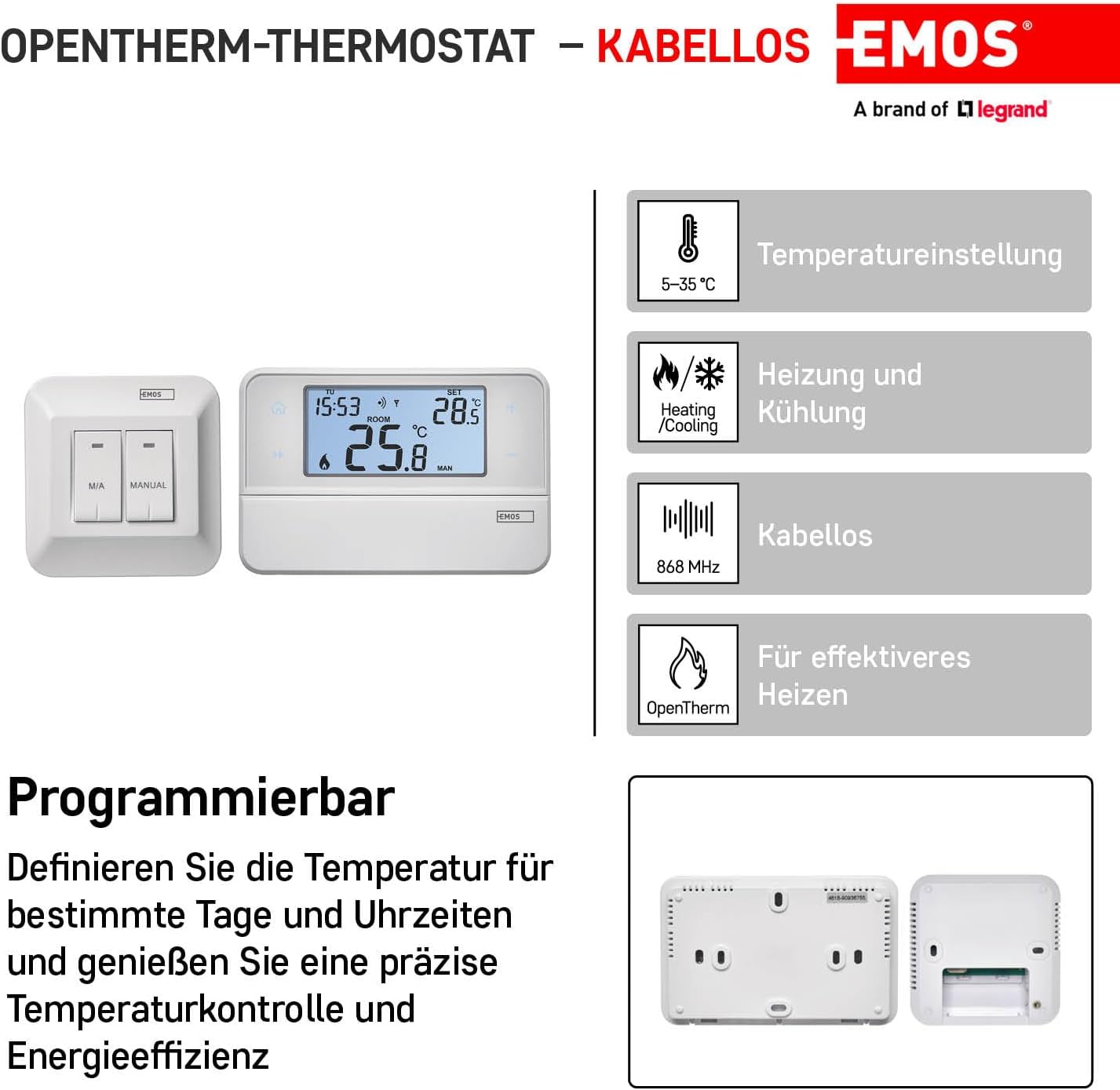
Figure 2: Overview of thermostat features including temperature setting, heating/cooling, wireless function, and OpenTherm compatibility.
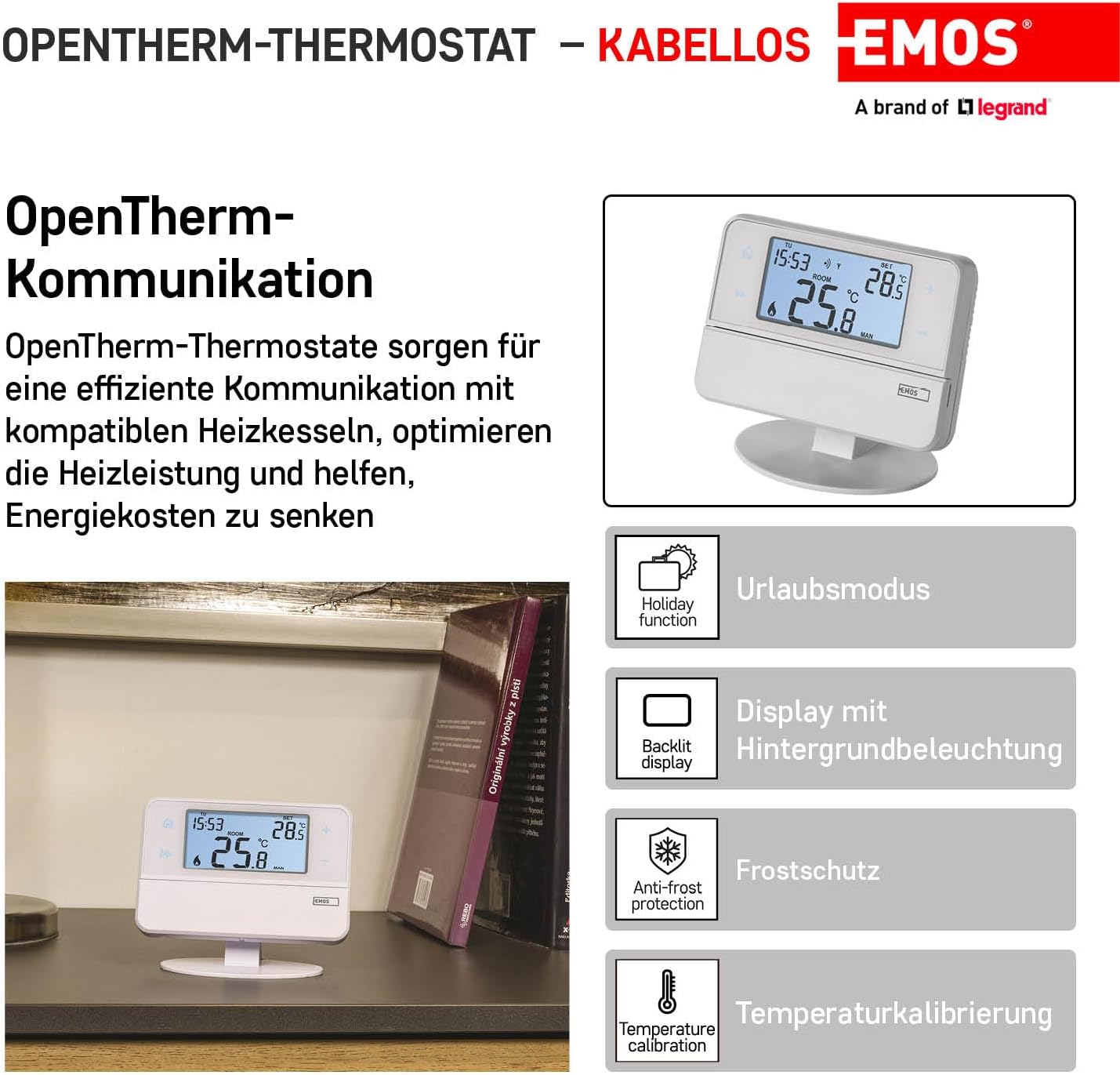
Figure 3: Details on OpenTherm communication, holiday function, backlit display, anti-frost protection, and temperature calibration.
Specifications
| Specification | Value |
|---|---|
| Product Dimensions (L x W x H) | 12.6 x 8.4 x 2.6 cm |
| Weight | 530 grams |
| Specific Use Instructions | Heating |
| Special Specifications | OpenTherm |
| Batteries Required | Yes (2 x AA for Transmitter) |
| Included Parts | 2 AA batteries, detailed instruction manual (German), mounting bracket |
| Item Model Number | P5616OT |
| Brand | EMOS |
| Controller Type | Manual Control |
| Special Feature | Holiday Mode |
| Color | White |
| Temperature Control Type | User Manual (French) - Note: Original manual may be in German, French version available online. |
| Connectivity Technology | RF (Radio Frequency) |
| Power Source | Battery Powered (Transmitter), Mains Powered (Receiver) |
Installation
Important: Ensure the main power supply to your heating/air conditioning system is disconnected before proceeding with installation. This prevents potential electrical hazards. Installation should be carried out by a qualified professional.
Thermostat Placement
The location of the thermostat significantly impacts its performance. Choose a room where family members spend most of their time. Ideally, place it on an interior wall where air circulates freely and away from direct sunlight. Avoid placing the thermostat near heat sources (e.g., televisions, radiators, refrigerators) or near a door (due to frequent shocks or vibrations). Failure to follow these recommendations may result in inaccurate temperature control.
Transmitter Installation
The transmitter can be mounted on the provided stand or directly on a wall.
- Remove the rear cover of the transmitter.
- Mark the positions for the mounting holes on the wall.
- Drill two holes, carefully insert the plastic wall plugs, and use two screws to secure the rear cover to the wall.
- Complete the installation by attaching the transmitter unit onto the fixed rear cover.
Receiver Installation
The receiver unit is typically mounted near the heating system.
- Remove the front cover of the receiver. Use a screwdriver to press and hold the inner lock, then remove the front cover.
- Mark the positions for the mounting holes on the wall.
- Drill two holes, carefully insert the plastic wall plugs, and use two screws to secure the rear cover of the receiver to the wall.
- Connect the wires to the labeled terminals according to the appropriate wiring diagram for your heating system.
- Complete the installation by attaching the receiver unit onto the fixed rear cover.

Figure 4: Rear view of the receiver showing wiring terminals (NO, NC, COM, L, N, OT).
Wiring Diagrams
Refer to the specific wiring diagram provided with your product or consult a qualified electrician for correct connection to your heating system. Common connection types include:
- Normally Open (NO) contact
- Normally Closed (NC) contact
- Common (COM) switching contact
- 230 V AC electrical connection (L - Live, N - Neutral)
- Pump/Motorized Valve Wiring Diagram
- Floor Heating Wiring Diagram
- Boiler Wiring Diagram
- Electric Actuator Wiring Diagram
- OpenTherm Connection (OT terminals)
Setup
Initial Power-Up
- Remove the front cover of the transmitter.
- Insert 2 x 1.5V AA alkaline batteries into the battery compartment. Do not use 1.2V rechargeable batteries as they may cause incorrect low battery indications.
- Inserting the batteries will power on the thermostat and activate the display. If the thermostat does not function correctly, check the battery polarity and charge level.
- If the heating/air conditioning system will not be used for an extended period, it is recommended to switch off the receiver unit (move the main switch to the '0' position).
Pairing Units (Transmitter and Receiver)
- Turn on the receiver by pressing the ON/OFF button on the left side of the receiver.
- Press and hold the M/A button on the receiver for 10 seconds until a green LED starts flashing on the receiver.
- On the transmitter, move the slider to the OFF position. Then, press and hold the 'H' and 'A' buttons simultaneously for 3 seconds until the green LED on the receiver stops flashing.
- The units are now paired, and the pairing icon will be displayed on the transmitter.
- If pairing fails, a different icon will be displayed. To change the pairing code, repeat the entire pairing procedure from step 1; the pairing code will be automatically overwritten.
- If the thermostat is not working correctly after pairing, verify battery polarity and charge, or reset the thermostat by removing and reinserting the batteries.
Wireless Communication Test
- Set a temperature on the transmitter several degrees higher than the current room temperature.
- The red LED on the receiver unit should illuminate, indicating that the relay is switched on.
- If the LED does not light up, move the transmitter closer to the receiver unit. The maximum range between the control unit and the switching unit is 80 meters in open space. This range may decrease indoors due to walls and other obstacles.
Operation

Figure 5: Front view of the transmitter showing the display and control buttons.
Display Description (Refer to Figure 5)
- Days of the week
- Time
- Room Temperature
- Heating Indicator (Flame icon)
- Set Temperature
- Selected Program (PROG)
- Holiday Mode Symbol
- Display Lock
- Temporary Mode Symbol
- Automatic Mode (AUTO) Symbol
- Manual Mode (MAN) Symbol
- Low Battery Indicator
- Cooling Indicator
- Units Pairing Icon
- Wireless Communication Icon
Control Elements Description (Refer to Figure 5)
- Home (Return to home screen)
- Next (Move to next option in current function)
- Adjust Value Setting (+/- buttons)
- Confirm (Confirm function selection)
- Copy
- Holiday Mode Button
- Battery Compartment
- Time and Date Setting
- Select and Modify Program (PROG)
- Anti-frost Mode (OFF)
- Manual Mode (MAN)
- Automatic Mode (AUTO)
LED Indicators on Receiver
- Automatic Mode: A red LED illuminates when the thermostat switches on the output relay (heating active).
- Manual Mode: Press the MANUAL button; a green LED will illuminate. To switch on the output relay, press the M/A button; a red LED will illuminate. To deactivate manual mode, press the MANUAL button again; the green LED will turn off.
Programming
Factory Pre-set Programs
This programmable indoor thermostat is designed for ease of use, with factory pre-set times and temperatures suitable for most users. These programs divide the day into 6 periods. If you wish to use a factory pre-set program, simply move the slider on the transmitter to the AUTO position to activate automatic mode.
User-Adjustable Programming
You can customize the heating schedule to fit your specific needs. The thermostat allows for 6 temperature changes per day. You can set different programs for weekdays and weekends, or individual days.
When modifying programs, be aware that changing the start time of the first program period (P1) will shift the subsequent program period times accordingly, but the total number of 6 periods remains fixed.
Refer to the detailed instruction manual (often available online from the manufacturer's website) for step-by-step guidance on setting custom programs, including time and temperature adjustments for each period.
Troubleshooting
| Problem | Possible Cause / Solution |
|---|---|
| Thermostat not working / Display off | Check battery polarity and charge level in the transmitter. Replace batteries if low. Ensure the receiver is powered on. Try resetting the thermostat by removing and reinserting batteries. |
| Units not pairing / Communication issues | Ensure both units are in pairing mode as described in the 'Pairing Units' section. Reduce the distance between the transmitter and receiver. Obstacles like thick walls can reduce wireless range. Repeat the pairing procedure. |
| Inaccurate temperature reading | Ensure the thermostat is not placed near heat sources, direct sunlight, or drafts. The temperature sensor may be slow to react; allow time for it to stabilize. The display temperature can be calibrated if necessary (refer to detailed manual). |
| Low battery warning appears frequently | Ensure you are using 1.5V alkaline batteries. This thermostat is not compatible with 1.2V rechargeable batteries, which can trigger false low battery warnings. |
| Cannot maintain set temperature in manual mode | Some users have reported this. Ensure the thermostat is not switching back to a programmed mode. Verify settings in the detailed manual. |
| Display beep is too loud / cannot be turned off | This is a known characteristic of the device and cannot be adjusted. |
Maintenance
Battery Replacement
When the low battery indicator appears on the transmitter display, replace the 2 x AA batteries promptly. Use only 1.5V alkaline batteries. Do not use 1.2V rechargeable batteries.
Cleaning
To clean the thermostat, wipe it with a soft, dry cloth. Do not use abrasive cleaners, solvents, or chemical agents, as these can damage the device.
Warranty and Support
Warranty Information
The EMOS Wireless Room Thermostat comes with a 2-year warranty. Please retain your proof of purchase for warranty claims.
Further Support
For more detailed instructions, advanced programming options, or specific wiring diagrams not fully covered in this manual, please refer to the comprehensive instruction manual available on the EMOS manufacturer's website. Search for model P5616OT. If you encounter persistent issues, contact EMOS customer support or a qualified technician.


