1. Introduction
This manual provides comprehensive instructions for the installation, operation, and maintenance of the Ubiquiti USW-Lite-8-PoE 8-Port Gigabit PoE Switch. This device is designed to expand your network connectivity and provide Power over Ethernet (PoE) to compatible devices such as access points, IP cameras, and VoIP phones. Please read this manual thoroughly before using the product to ensure proper setup and functionality.
2. Product Overview
The Ubiquiti USW-Lite-8-PoE is a compact, managed Gigabit switch featuring eight RJ45 Ethernet ports. Four of these ports support 802.3af/at PoE, enabling both data and power transmission over a single cable. The switch integrates seamlessly with the UniFi network ecosystem for centralized management.
2.1 Front Panel
The front panel of the USW-Lite-8-PoE features eight Gigabit Ethernet ports and LED indicators for status monitoring.

Image: This image displays the Ubiquiti USW-Lite-8-PoE switch from a top-front angle, highlighting its compact white casing. The front panel features eight RJ45 Gigabit Ethernet ports, numbered 1 through 8. To the right of the ports, a vertical column of LED indicators provides status for PoE (Power over Ethernet), 802.3af/at standard, link activity (Link/Down), and connection speed (10/100/1000 Mbps). A small blue LED on the far left indicates the device's overall status.
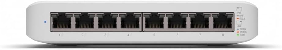
Image: A direct front view of the Ubiquiti USW-Lite-8-PoE switch, focusing on the eight Gigabit Ethernet ports and their corresponding LED indicators. Each port is clearly numbered. The LEDs on the right provide visual feedback on PoE status (PoE, OFF, 802.3), link status (Link, Down), and speed (10/100, 1000 Mbps). A single blue LED on the left indicates the device's operational status.
LED Indicators:
- System LED (Left):
- Blue: Device is ready for use.
- Flashing Blue: Device is busy or undergoing firmware upgrade.
- White: Device is factory default, waiting for adoption.
- PoE LED (Right, per port 1-4):
- Green: PoE is active on the port.
- Off: No PoE output.
- Link/Activity LED (Right, per port 1-8):
- Green: 1 Gbps link established. Flashing indicates activity.
- Amber: 10/100 Mbps link established. Flashing indicates activity.
- Off: No link.
2.2 Rear Panel
The rear panel contains the power input port.

Image: This image shows the rear panel of the Ubiquiti USW-Lite-8-PoE switch. The only visible feature is the circular 54VDC power input port, centrally located, indicating where the external power adapter connects to the device.
2.3 Bottom Panel
The bottom panel includes mounting points for installation.

Image: The bottom of the Ubiquiti USW-Lite-8-PoE switch is shown, featuring two recessed areas designed for wall mounting. The central area contains the product label with model information, serial number, and regulatory compliance markings. These slots allow for secure attachment to a flat surface.
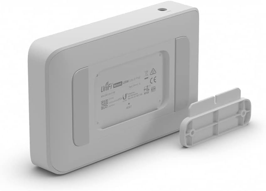
Image: This image presents the bottom of the Ubiquiti USW-Lite-8-PoE switch alongside its detached wall-mounting bracket. The bracket is designed to fit into the recessed slots on the switch's underside, facilitating secure installation on a wall or other flat surface.
3. Setup
3.1 Package Contents
- USW-Lite-8-PoE Switch
- Power Adapter
- Wall Mount Bracket (optional, may be included)
- Screws and Wall Plugs (optional, for mounting)
3.2 Physical Installation
- Placement: Position the switch on a flat, stable surface or mount it to a wall. Ensure adequate ventilation around the device.
- Mounting (Optional): If wall-mounting, use the provided bracket and hardware. Secure the bracket to the desired location, then slide the switch onto the bracket until it clicks into place.
3.3 Connecting Power
- Connect the included power adapter to the 54VDC input port on the rear of the USW-Lite-8-PoE.
- Plug the power adapter into a suitable power outlet. The System LED will illuminate to indicate power.
3.4 Connecting Network Devices
- Connect your network devices (e.g., router, other switches, computers) to any of the eight RJ45 Ethernet ports using standard Ethernet cables.
- For devices requiring Power over Ethernet (PoE), connect them to ports 1-4. The switch will automatically detect and provide PoE if the device is compatible.
3.5 Initial Configuration (UniFi Controller)
The USW-Lite-8-PoE is managed via the Ubiquiti UniFi Controller software. Ensure you have a UniFi Controller running on your network (either a dedicated UniFi Cloud Key, a UniFi Dream Machine, or software installed on a computer/server).
- Ensure the switch is powered on and connected to your network where the UniFi Controller is accessible.
- Open your UniFi Controller interface. The switch should appear as a pending device.
- Follow the on-screen prompts within the UniFi Controller to 'Adopt' the USW-Lite-8-PoE into your network.
- Once adopted, you can configure port settings, VLANs, PoE output, and monitor device status through the Controller interface.
4. Operating Instructions
4.1 Basic Network Connectivity
Once powered on and connected, the USW-Lite-8-PoE functions as a standard Gigabit Ethernet switch, forwarding data traffic between connected devices. The Link/Activity LEDs will indicate active connections and data transfer.
4.2 Power over Ethernet (PoE) Functionality
Ports 1-4 of the USW-Lite-8-PoE support 802.3af/at PoE. When a compatible PoE device is connected to one of these ports, the switch will automatically negotiate and supply power. The PoE LED for that port will illuminate green.
4.3 Monitoring and Management
All advanced monitoring and management of the switch, including port statistics, firmware updates, and configuration changes, are performed through the UniFi Controller interface. Refer to the UniFi Controller documentation for detailed instructions on managing your network devices.
5. Maintenance
5.1 Cleaning
To clean the switch, use a soft, dry cloth. Do not use liquid cleaners or aerosol sprays, as they may damage the device. Ensure the device is powered off before cleaning.
5.2 Firmware Updates
Firmware updates are crucial for maintaining optimal performance, security, and access to new features. These updates are managed through the UniFi Controller. Regularly check the Controller for available firmware updates and apply them as recommended.
5.3 Environmental Considerations
Ensure the switch is operated within its specified temperature and humidity ranges. Avoid placing the device in direct sunlight, near heat sources, or in areas with excessive dust or moisture. Maintain proper airflow around the device to prevent overheating.
6. Troubleshooting
6.1 No Power
- Verify the power adapter is securely connected to both the switch and a working power outlet.
- Check if the power outlet is functional by plugging in another device.
- Ensure the power adapter is the original one supplied with the device or a compatible replacement.
6.2 No Link/Activity on Port
- Ensure the Ethernet cable is securely connected at both ends.
- Try a different Ethernet cable to rule out cable failure.
- Connect a different device to the port to check if the issue is with the connected device.
- Check the UniFi Controller for port status and configuration.
6.3 PoE Not Working on Ports 1-4
- Verify that the connected device is PoE compatible (802.3af/at).
- Ensure the device is connected to one of the PoE-enabled ports (1-4).
- Check the UniFi Controller to confirm PoE is enabled for the specific port.
- Ensure the total power budget of the switch is not exceeded.
6.4 Device Not Appearing in UniFi Controller
- Ensure the switch is powered on and connected to the same network segment as your UniFi Controller.
- Verify that the UniFi Controller software is running and accessible.
- Try restarting the switch.
- If the System LED is white, the device is in a factory default state and should be discoverable. If not, perform a factory reset.
6.5 Factory Reset
To perform a factory reset, locate the small reset button on the device (often a pinhole). With the device powered on, use a paperclip or similar pointed object to press and hold the reset button for approximately 10 seconds. Release the button when the System LED starts flashing. The device will then reboot to factory default settings.
7. Specifications
| Feature | Specification |
|---|---|
| Model | USW-LITE-8-POE |
| Dimensions (L x W x H) | 6.44" x 3.92" x 1.25" (163.7 x 99.5 x 31.7 mm) |
| Weight | 0.71 kg (1.56 lbs) |
| Networking Interfaces | (8) 10/100/1000 Mbps RJ45 Ports |
| PoE Interfaces | (4) 802.3af/at PoE Ports (Ports 1-4) |
| Max. Power Consumption | 12W (Switch only) / 52W (with PoE output) |
| Power Method | 54VDC, 1.1A Power Adapter (Included) |
| Operating Temperature | -15 to 40° C (5 to 104° F) |
| Operating Humidity | 10 to 90% Non-condensing |
| Case Material | Plastic |
| Certifications | CE, FCC, IC |
8. Warranty and Support
For technical support, warranty information, and additional resources, please visit the official Ubiquiti Networks website. You can find detailed product documentation, community forums, and contact information for customer service there.
Ubiquiti Networks Official Website: www.ui.com


