1. Introduction
The OWON SDS1104 is a 4-channel digital storage oscilloscope designed for high accuracy and performance in various electrical testing and measurement applications. It features a 100MHz bandwidth and a 1GS/s sample rate, making it suitable for detailed waveform analysis.
This manual provides essential information for the proper setup, operation, and maintenance of your SDS1104 oscilloscope. Please read it thoroughly before using the device.

Figure 1.1: Front view of the OWON SDS1104 Digital Oscilloscope.
2. Key Features
- Bandwidth: 100MHz with 4 independent channels.
- Sample Rate: Up to 1GS/s real-time sample rate.
- Record Length: 40M record length for detailed signal capture.
- Waveform Refresh Rate: 45,000 wfms/s for quick observation of signal changes.
- Display: 8-inch 800x600 high-resolution LCD for clear waveform display.
- Connectivity: SCPI and LabVIEW supported for remote control and data analysis.
- Trigger Functions: Multi-trigger options including Edge, Video, Pulse, Slope, Runt, Windows, Timeout, Nth Edge, Logic, I2C, SPI, RS232, CAN (optional).
- Automatic Measurements: Built-in functions for 39 types of automatic measurements.
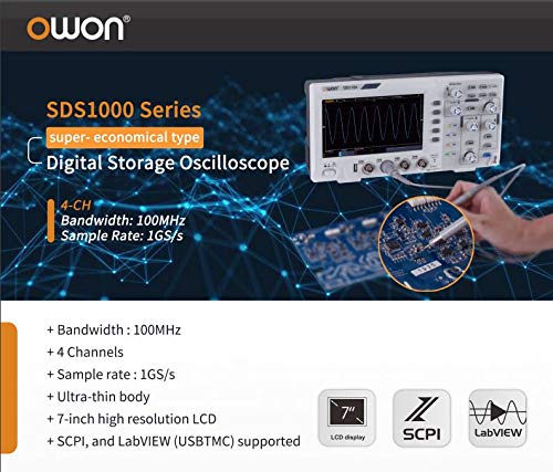
Figure 2.1: Overview of key features for the SDS1000 series, including 100MHz bandwidth, 4 channels, 1GS/s sample rate, ultra-thin body, 7-inch high resolution LCD, and SCPI/LabVIEW support.
3. Product Overview and Controls
3.1 Front Panel
The front panel of the SDS1104 features the display, control knobs, function buttons, and input channels. Understanding the layout is crucial for efficient operation.
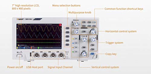
Figure 3.1: Labeled front panel of the SDS1104, showing the 7-inch high resolution LCD, menu selection buttons, multipurpose knob, common function shortcut keys, horizontal control system, trigger system, copy key, vertical control system, signal input channels (CH1-CH4), USB Host port, and power on/off button.
- Display: 7-inch high resolution LCD (800x480 pixels) for waveform visualization.
- Menu Selection Buttons: Navigate through on-screen menus.
- Multipurpose Knob: Adjust various parameters and settings.
- Common Function Shortcut Keys: Quick access to frequently used functions.
- Horizontal Control System: Adjust time base and horizontal position.
- Trigger System: Control trigger level, mode, and type.
- Copy Key: Quickly save or copy screen content.
- Vertical Control System: Adjust vertical scale (Volts/Div) and position for each channel.
- Signal Input Channels (CH1-CH4): BNC connectors for probe input.
- USB Host Port: For connecting USB storage devices.
- Power On/Off: Main power switch.
3.2 Rear Panel and Side Connections
The rear and side panels house additional ports and features for connectivity and stability.
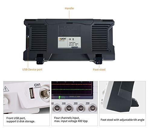
Figure 3.2: Rear view of the SDS1104, highlighting the USB Device port, handle, and foot stools for tilt adjustment.
- USB Device Port: Connects the oscilloscope to a computer for data transfer and remote control.
- Handle: For easy portability.
- Foot Stools: Adjustable feet to tilt the oscilloscope for better viewing angles.
4. Setup and Initial Operation
4.1 Unpacking and Inspection
Upon receiving your SDS1104, carefully unpack all components and inspect for any signs of damage. Retain the packaging for future transport or storage.
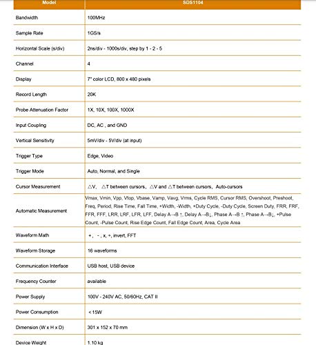
Figure 4.1: Contents of the SDS1000 package, including the SDS1000 unit, four probes, USB cable, probe adjustment tool, power cord, and a CD-ROM with quick guide.
The standard package includes:
- SDS1104 Oscilloscope Unit
- Probe x 4
- USB Cable
- Probe Adjustment Tool
- Power Cord
- CD-ROM and Quick Guide
4.2 Power Connection
Connect the supplied power cord to the AC input on the rear panel of the oscilloscope and then to a suitable AC power outlet (100V - 240V AC, 50/60Hz).
4.3 Probe Connection and Compensation
Connect the oscilloscope probes to the BNC input connectors (CH1-CH4) on the front panel. It is recommended to compensate the probes before making critical measurements to ensure accurate readings.
- Connect the probe to CH1.
- Connect the probe tip to the probe compensation signal output (usually a square wave test point on the front panel).
- Adjust the probe compensation screw (on the probe body) until a flat-top square wave is displayed on the screen.
5. Operating the Oscilloscope
5.1 Basic Waveform Display
After power-on, press the AUTO button to automatically adjust the vertical and horizontal settings for a stable waveform display. Use the vertical (Volts/Div) and horizontal (Time/Div) knobs to fine-tune the display.
5.2 Automatic Measurements
The SDS1104 offers 39 types of automatic measurements, providing quick and accurate analysis of waveform parameters.
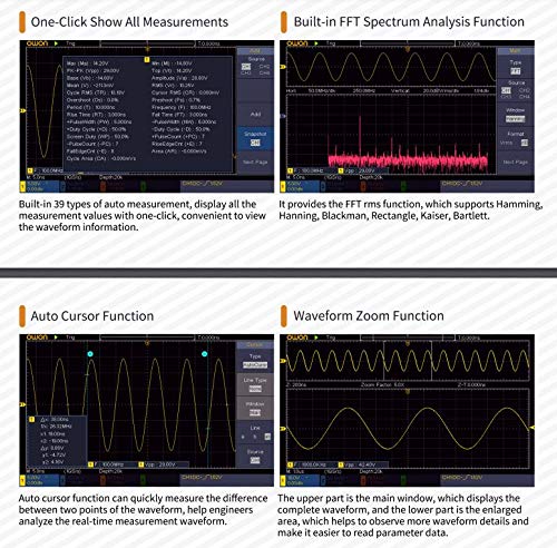
Figure 5.1: Screen showing built-in 39 types of auto measurements and the FFT spectrum analysis function. Measurements include Max, Min, Pk-Pk, RMS, Mean, Frequency, Period, Rise Time, Fall Time, and more. The FFT function supports Hamming, Hanning, Blackman, Rectangle, Kaiser, and Bartlett windows.
To access automatic measurements, press the MEASURE button. You can select various parameters such as Period, Frequency, Mean, PK-PK, RMS, Max, Min, Rise Time, Fall Time, etc.
5.3 Cursor and Zoom Functions
The oscilloscope provides auto cursor and waveform zoom functions for detailed analysis of specific waveform sections.
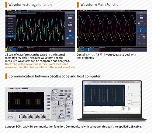
Figure 5.2: Display illustrating the Auto Cursor function for measuring differences between two points on a waveform, and the Waveform Zoom function for enlarging specific areas of the waveform for detailed observation.
- Auto Cursor: Automatically places cursors to measure parameters like voltage difference (ΔV) and time difference (ΔT).
- Waveform Zoom: Enlarge a specific portion of the waveform for closer inspection.
5.4 Waveform Storage and Math Functions
The SDS1104 allows saving waveforms and performing mathematical operations on them.
Figure 5.3: Screen demonstrating the Waveform Storage function, allowing up to 16 sets of waveforms to be saved and compared, and the Waveform Math Function, which includes operations like +, -, ×, /, FFT, and invert.
- Waveform Storage: Save up to 16 sets of waveforms to internal memory or a USB disk for later recall and analysis.
- Waveform Math: Perform operations such as addition, subtraction, multiplication, division, FFT (Fast Fourier Transform), and inversion on waveforms.
5.5 PC Communication
The oscilloscope can be connected to a host computer for remote control, data logging, and advanced analysis using SCPI commands or LabVIEW software.
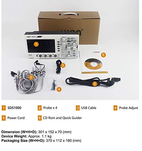
Figure 5.4: Illustration of the SDS1104 communicating with a computer via the supplied USB cable, supporting SCPI and LabVIEW communication functions.
Use the provided USB cable to connect the oscilloscope's USB Device port to your computer. Install the necessary drivers and software (available on the included CD-ROM or OWON's website) to establish communication.
6. Maintenance
Proper maintenance ensures the longevity and accuracy of your SDS1104 oscilloscope.
- Cleaning: Use a soft, damp cloth to clean the exterior of the oscilloscope. Do not use abrasive cleaners or solvents. Ensure the device is powered off and unplugged before cleaning.
- Storage: When not in use, store the oscilloscope in a dry, dust-free environment, away from direct sunlight and extreme temperatures.
- Probe Care: Handle probes carefully. Avoid bending or kinking the cables. Store them properly to prevent damage to the tips and connectors.
- Calibration: Periodic calibration by qualified personnel is recommended to maintain measurement accuracy, especially after significant temperature changes or prolonged use.
7. Troubleshooting
This section addresses common issues you might encounter with your SDS1104 oscilloscope.
| Problem | Possible Cause | Solution |
|---|---|---|
| No display after power on. | Power cord not connected, power switch off, power supply issue. | Check power cord connection, ensure power switch is on, try a different power outlet. |
| No waveform displayed. | Probe not connected, signal too small/large, trigger not set correctly, channel off. | Connect probe, adjust vertical scale (Volts/Div), press AUTO, check trigger settings, ensure channel is enabled. |
| Unstable waveform. | Incorrect trigger level or mode, noisy signal. | Adjust trigger level, change trigger mode (e.g., Edge, Auto), check signal source for noise. |
| Incorrect measurements. | Probe compensation incorrect, wrong probe attenuation setting. | Perform probe compensation, ensure probe attenuation (e.g., 1X, 10X) matches oscilloscope setting. |
If the problem persists after attempting these solutions, please contact OWON customer support.
8. Specifications
Detailed technical specifications for the OWON SDS1104 oscilloscope.
| Parameter | Specification |
|---|---|
| Model | SDS1104 |
| Bandwidth | 100MHz |
| Channels | 4 |
| Sample Rate (Real-time) | Single CH: 1 GSa/s, Dual CH: 500 MSa/s, Four CH: 250 MSa/s |
| Waveform Capture Rate | 45,000 wfms/s |
| Display | 8" color LCD, TFT display, 800×600 pixels |
| Max Record Length | 40M (one channel), 20M (two channels), 10M (four channels) |
| Input Coupling | DC, AC, Ground |
| Input Impedance | 1MΩ±2%, in parallel with 15pF±5pF |
| Max Input Voltage | 400 V (DC + AC Peak) |
| Vertical Sensitivity | 1 mV/div - 10 V/div |
| Trigger Type | Edge, Video, Pulse, Slope, Runt, Windows, Timeout, Nth Edge, Logic, I2C, SPI, RS232, CAN (optional) |
| Decoding Type (optional) | RS232, I2C, SPI, CAN |
| Automatic Measurement | Period, Frequency, Mean, PK-PK, RMS, Max, Min, Top, Base, Amplitude, Overshoot, Preshoot, Rise Time, Fall Time, +Pulse Width, -Pulse Width, +Duty Cycle, -Duty Cycle, Delay A→B↑, Delay A→B↓, Phase A→B↑, Phase A→B↓, +Pulse Count, -Pulse Count, Rise Edge Count, Fall Edge Count, Area, Cycle Area |
| Waveform Math | +, -, ×, /, FFT, Invert |
| Waveform Storage | 16 waveforms |
| Communication Interface | USB host, USB device |
| Power Supply | 100V - 240V AC, 50/60Hz, CAT II |
| Power Consumption | <15W |
| Dimension (W×H×D) | 301 × 152 × 70 mm |
| Device Weight | Approx. 1.1 kg |
9. Warranty and Support
OWON products are manufactured under strict quality control standards. For warranty information, please refer to the warranty card included with your product or visit the official OWON website.
For technical support, troubleshooting assistance beyond this manual, or service inquiries, please contact OWON customer service through their official channels. Ensure you have your product model (SDS1104) and serial number ready when contacting support.
OWON Official Website: www.owon.com.hk


