
1. Safety Information
Please read and understand all safety information and operating instructions before using this multimeter. Failure to follow these instructions may result in electric shock, fire, or damage to the meter.
- Always ensure the test leads are properly connected and the function switch is set to the correct range before making any measurements.
- Do not attempt to measure voltages or currents exceeding the maximum rated values for this meter.
- Exercise extreme caution when working with live circuits. High voltages can be dangerous.
- Never open the meter casing unless specifically instructed for battery or fuse replacement. Ensure test leads are disconnected before opening.
- Replace the battery when the low battery indicator appears to ensure accurate readings.
- Do not use the meter if it appears damaged or if the insulation on the test leads is compromised.
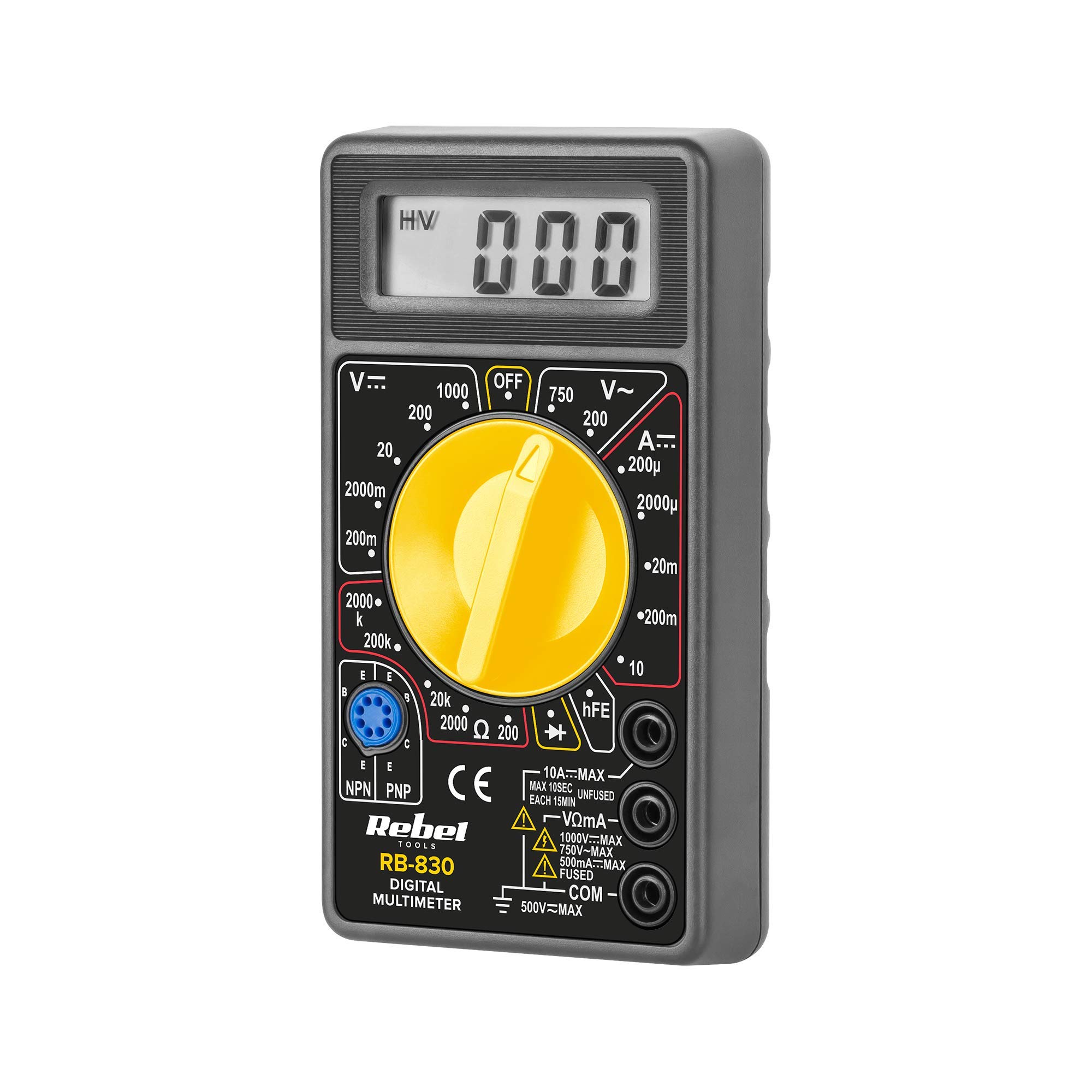
Figure 1: Rear view of the Rebel MIE-RB-830 Multimeter, showing the battery compartment cover and a warning label. The label advises removing test leads before opening the case to avoid electrical shock and to install fuses with correct amp/volt ratings. It also indicates the power supply is a 9V battery, type NEDA 1604 9V 6F22.
2. Product Overview
The Rebel MIE-RB-830 is a compact, battery-operated digital multimeter designed for measuring DC/AC voltage, DC current, resistance, diode, and transistor (hFE) values. It is suitable for general electrical testing and troubleshooting.
2.1. Components
- Digital Multimeter Unit
- Test Leads (Red and Black)
- 9V Battery (may be included or sold separately)
- User Manual (this document)

Figure 2: The Rebel MIE-RB-830 Digital Multimeter shown with its accompanying red and black test leads. The multimeter features a large LCD display and a rotary function switch.

Figure 3: Close-up view of the red and black test leads. These leads are essential for connecting the multimeter to the circuit under test.
3. Setup
3.1. Battery Installation
- Ensure the multimeter is turned OFF and all test leads are disconnected.
- Locate the battery compartment cover on the back of the meter (refer to Figure 1).
- Unscrew the retaining screw(s) and carefully remove the cover.
- Insert a new 9V battery (NEDA 1604 or 6F22 type), observing the correct polarity (+ and -).
- Replace the battery compartment cover and secure it with the screw(s).
3.2. Connecting Test Leads
- Connect the red test lead to the "VΩmA" input jack.
- Connect the black test lead to the "COM" (common) input jack.
- For current measurements exceeding 200mA (up to 10A), connect the red test lead to the "10A" input jack.
4. Operating Instructions
4.1. Function Selection
Turn the rotary switch to the desired measurement function and range. Always start with a higher range if the approximate value is unknown to prevent overloading the meter.
4.2. Measuring DC Voltage (V–)
- Set the rotary switch to the desired DC Voltage (V–) range (e.g., 20V, 200V).
- Connect the red test lead to the positive (+) side of the circuit and the black test lead to the negative (-) side.
- Read the voltage value on the LCD display.
4.3. Measuring AC Voltage (V∼)
- Set the rotary switch to the desired AC Voltage (V∼) range (e.g., 200V, 750V).
- Connect the test leads across the AC voltage source.
- Read the voltage value on the LCD display.
4.4. Measuring DC Current (A–)
Caution: To measure current, the meter must be connected in series with the circuit. Never connect the meter in parallel with a voltage source when in current mode, as this can damage the meter and the circuit.
- Set the rotary switch to the desired DC Current (A–) range (e.g., 20mA, 200mA, 10A).
- For currents up to 200mA, ensure the red lead is in the "VΩmA" jack. For currents up to 10A, move the red lead to the "10A" jack.
- Open the circuit where current is to be measured and connect the meter in series.
- Read the current value on the LCD display.
4.5. Measuring Resistance (Ω)
Caution: Ensure the circuit or component under test is de-energized before measuring resistance.
- Set the rotary switch to the desired Resistance (Ω) range (e.g., 200Ω, 2kΩ, 200kΩ).
- Connect the test leads across the component or circuit to be measured.
- Read the resistance value on the LCD display.
4.6. Diode Test (→|–)
- Set the rotary switch to the Diode Test (→|–) position.
- Connect the red test lead to the anode of the diode and the black test lead to the cathode.
- The display will show the forward voltage drop (typically 0.5V to 0.8V for silicon diodes).
- Reverse the leads. The display should show "OL" (Open Loop) for a good diode.
4.7. Transistor (hFE) Test
- Set the rotary switch to the hFE position.
- Identify if the transistor is NPN or PNP.
- Insert the transistor's emitter, base, and collector leads into the corresponding sockets on the hFE test socket.
- Read the hFE (DC current gain) value on the display.
5. Maintenance
5.1. Battery Replacement
When the low battery indicator appears on the display, replace the 9V battery as described in Section 3.1. Using a low battery can lead to inaccurate readings.
5.2. Fuse Replacement
If the current measurement function stops working, the fuse may need replacement. This operation should only be performed by qualified personnel.
- Ensure the multimeter is turned OFF and all test leads are disconnected.
- Open the back casing of the meter (this may involve more screws than just the battery compartment).
- Locate the blown fuse and replace it with a fuse of the exact same type and rating (e.g., F200mA/250V for mA range, F10A/250V for 10A range). Refer to the internal markings or specifications for precise fuse ratings.
- Carefully reassemble the meter, ensuring all screws are tightened.
5.3. Cleaning
Wipe the meter with a damp cloth and mild detergent. Do not use abrasives or solvents. Keep the meter dry.
6. Troubleshooting
| Problem | Possible Cause | Solution |
|---|---|---|
| No display or faint display | Low or dead battery | Replace the 9V battery. |
| Incorrect readings | Low battery; Incorrect range selection; Poor test lead connection | Replace battery; Select appropriate range; Ensure leads are firmly connected. |
| Current measurement not working | Blown fuse; Incorrect lead connection for current | Replace fuse (see Section 5.2); Ensure red lead is in "VΩmA" or "10A" jack as appropriate. |
| "OL" (Overload) displayed | Measured value exceeds selected range; Open circuit (for resistance/continuity) | Select a higher range; Check circuit for breaks. |
7. Specifications
| Measurement Function | Range | Accuracy |
|---|---|---|
| DC Voltage (V–) | 200mV, 2V, 20V, 200V, 1000V | ±(0.5% + 2 digits) |
| AC Voltage (V∼) | 200V, 750V | ±(1.2% + 10 digits) |
| DC Current (A–) | 200µA, 2mA, 20mA, 200mA, 10A | ±(1.0% + 2 digits) |
| Resistance (Ω) | 200Ω, 2kΩ, 20kΩ, 200kΩ, 2MΩ | ±(0.8% + 2 digits) |
| Diode Test | Yes | Forward voltage drop |
| Transistor (hFE) Test | Yes | hFE value |
| Power Supply | 9V Battery (NEDA 1604 or 6F22) | |
| Display | 3½ Digit LCD, Max. 1999 | |
| Dimensions | Approx. 13.5 x 10 x 4 cm | |
| Weight | Approx. 107 grams (without battery) | |
| Operating Temperature | 0°C to 40°C (32°F to 104°F) | |
| Storage Temperature | -10°C to 50°C (14°F to 122°F) | |
| Safety Standards | CE, RoHS |
8. Warranty and Support
This Rebel MIE-RB-830 Digital Multimeter is covered by a standard manufacturer's warranty against defects in materials and workmanship. Please refer to the warranty card included with your purchase or contact your retailer for specific warranty terms and conditions.
For technical support or service inquiries, please contact the point of purchase or visit the official Rebel website for contact information.


