1. Introduction
This manual provides detailed instructions for the installation, operation, and maintenance of the TAKEX Multi-Channel Receiver Unit RXF-3000A. This unit is designed to support crime prevention, disaster prevention, and security systems in large-scale properties such as buildings, facilities, and schools. Please read this manual thoroughly before use to ensure correct and safe operation.
2. Key Features
- Versatile Channel Options: Available in 10-channel (RXF-1000A), 20-channel (RXF-2000A), and 30-channel (RXF-3000A) configurations with individual outputs to suit various system scales.
- High Transmitter Capacity: Up to 60 transmitters can be registered and assigned across the available channels. For example, 60 units can be registered to a single channel, or 30 units each to two channels.
- 4-Frequency Switching Function: Allows selection and switching between four types of wireless frequencies, minimizing the risk of interference with other wireless systems.
- Clear LCD Display: An integrated LCD screen clearly displays critical information such as transmitter channel, registration number, serial number (S/No.), and abnormal conditions.
- Alarm Sound Activation: Upon receiving an alarm, the unit can activate either an alarm sound or a chime sound. Both sounds can be switched collectively.
- Flexible Registration Methods: Transmitters can be registered by transmitting a signal (alarm registration), by directly inputting the transmitter's serial number (S/No.) into the unit, or by using optional PC software.
- Comprehensive Output System: Equipped with one general alarm output circuit and four abnormal output circuits for tamper detection, environmental interference, low battery, and periodic transmission abnormalities.
- Alarm Memory Control: The alarm memory can be controlled in conjunction with the system's arming and disarming states.
- 4-Stage Radio Wave Level Display: In inspection mode, the reception status of radio waves from transmitters is indicated by both sound and a 4-stage LCD display.
- 4-Stage Noise Level Display: In radio wave environment inspection mode, the influence of interference waves and ambient noise can be checked, which assists in selecting an optimal installation location.
3. Product Overview
The TAKEX RXF-3000A is a multi-channel wireless receiver unit designed for robust security applications. It features a clear LCD display and multiple indicator lights for easy status monitoring.

Figure 1: Front view of the TAKEX RXF-3000A Multi-Channel Receiver Unit, showing the indicator lights, LCD screen, and antenna.
The unit's design allows for flexible integration into various security infrastructures, providing reliable reception and alert capabilities.

Figure 2: Diagram illustrating the key features and capabilities of the TAKEX RXF-3000A, including its multi-channel support and frequency switching.
4. Installation and Wiring
4.1 External Dimensions
Proper installation requires adherence to the unit's dimensions and mounting specifications. The diagram below provides detailed measurements for planning your installation.

Figure 3: External dimensions diagram of the RXF-3000A unit, including mounting points and cable entry locations.
4.2 Wiring Connections
The unit requires connection to a power source and external devices for alarm outputs. Ensure all wiring is performed by qualified personnel in accordance with local electrical codes.

Figure 4: Detailed diagram showing wiring connections for power, alarm outputs, and other interfaces, along with internal dimensions.
Refer to the diagram for terminal assignments and ensure correct polarity for power connections. The unit supports various output types for integration with existing security systems.
5. Transmitter Registration
The RXF-3000A offers multiple methods for registering wireless transmitters:
- Alarm Registration: Transmit a signal from the transmitter to register it with the receiver unit.
- Serial Number Registration: Directly input the transmitter's serial number (S/No.) into the RXF-3000A unit using the control panel.
- PC Software Registration: Utilize optional registration/deletion software on a personal computer for managing transmitter registrations. This method is recommended for large-scale systems.
Ensure that each transmitter is assigned to the correct channel during registration to maintain system organization and functionality.
6. Operation
6.1 Basic Operation
The unit's primary function is to receive signals from registered transmitters and trigger alarms or other outputs. The LCD display provides real-time status updates.
6.2 Frequency Switching
To change the operating frequency, access the frequency setting menu via the control panel. Select one of the four available frequencies to avoid interference with other wireless devices in the vicinity.
6.3 Inspection Mode
The inspection mode allows for checking the radio wave reception status and ambient noise levels:
- Radio Wave Level Check: In inspection mode, the reception strength from a transmitter is indicated by sound and a 4-stage display on the LCD.
- Noise Level Check: This mode helps identify interference waves and ambient noise, which is crucial for optimizing the unit's placement. The noise level is also displayed in 4 stages.
7. Maintenance and Troubleshooting
7.1 Maintenance
- Regular Checks: Periodically check the unit's indicator lights and LCD display for any abnormal conditions.
- Cleaning: Clean the unit's exterior with a soft, dry cloth. Do not use abrasive cleaners or solvents.
- Battery Replacement: While the receiver unit is mains-powered, ensure that batteries in associated wireless transmitters are replaced regularly as per their respective manuals.
7.2 Troubleshooting
If the unit is not functioning as expected, refer to the LCD display for error messages or abnormal conditions. Common issues and their potential solutions include:
- No Signal Reception: Check transmitter batteries, ensure transmitters are within range, and verify frequency settings. Use inspection mode to check radio wave levels.
- False Alarms: Check for environmental interference using the noise level check in inspection mode. Ensure transmitters are securely mounted and not subject to accidental activation.
- Display Errors: If the LCD shows unusual characters or no display, power cycle the unit. If the problem persists, contact support.
8. Technical Specifications
The following table details the technical specifications for the TAKEX RXF-3000A Multi-Channel Receiver Unit.
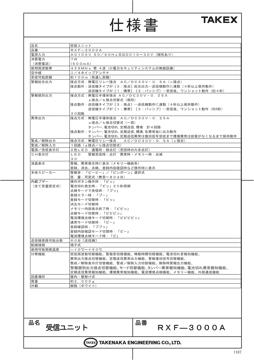
Figure 5: Detailed specifications table for the RXF-3000A, including electrical, operational, and physical characteristics.
| Item | Specification (RXF-3000A) |
|---|---|
| Product Name | Receiver Unit |
| Model | RXF-3000A (30 Channels) |
| Power Input | AC100V 50/60Hz or DC10-30V (Non-polarity) |
| Current Consumption | 400mA (at AC100V) / 150mA (at DC30V) |
| Operating Frequency Band | 426MHz band (4-frequency switching system) |
| Antenna | Rod antenna |
| Radio Wave Range | Approx. 100m (line of sight) |
| Alarm General Output | 1 circuit (a/b contact, AC/DC30V 0.5A) |
| Alarm Individual Output | 30 circuits (a/b contact, AC/DC30V 0.25A) |
| Abnormal Output | 4 circuits (Tamper, Environment, Battery Low, Periodic Transmission) |
| Arm/Disarm Output | 1 circuit (a/b contact, AC/DC30V 0.5A) |
| Display | LCD (backlight), LED (alarm, memory, time) |
| Sound | Main speaker, built-in buzzer |
| Registrable Units | Max 60 units |
| Operating Temperature | -10°C to +50°C |
| Dimensions | 240(W) x 340(H) x 60(D) mm (excluding antenna) |
| Weight | Approx. 2,000g |
| Casing Material | Resin (White) |
9. Support Information
For technical assistance, warranty claims, or further inquiries regarding your TAKEX RXF-3000A unit, please contact TAKEX customer support.
Manufacturer: TAKEX (Takenaka Engineering Co., Ltd.)
Please refer to the official TAKEX website or your local distributor for the most current contact information and support resources.


