1. Introduction
This user manual provides comprehensive instructions for the installation, operation, and maintenance of the Thincol AC Current Transducer (Model: BST-I-W1-A4-O5-P2). This device is designed to convert AC 0-5A current signals into DC 0-10V output signals, making it suitable for various industrial control and dispatching systems. Please read this manual thoroughly before using the product to ensure safe and efficient operation.
2. Safety Information
Always adhere to the following safety precautions to prevent injury or damage to the device:
- Ensure the power supply voltage matches the device's requirements (DC 24V ± 10%).
- Installation and wiring should only be performed by qualified personnel.
- Disconnect power before making any connections or adjustments.
- Do not expose the device to excessive moisture, dust, or extreme temperatures.
- Verify all connections are secure to prevent short circuits or improper operation.
- The device is designed for industrial applications; use it only for its intended purpose.
3. Product Overview
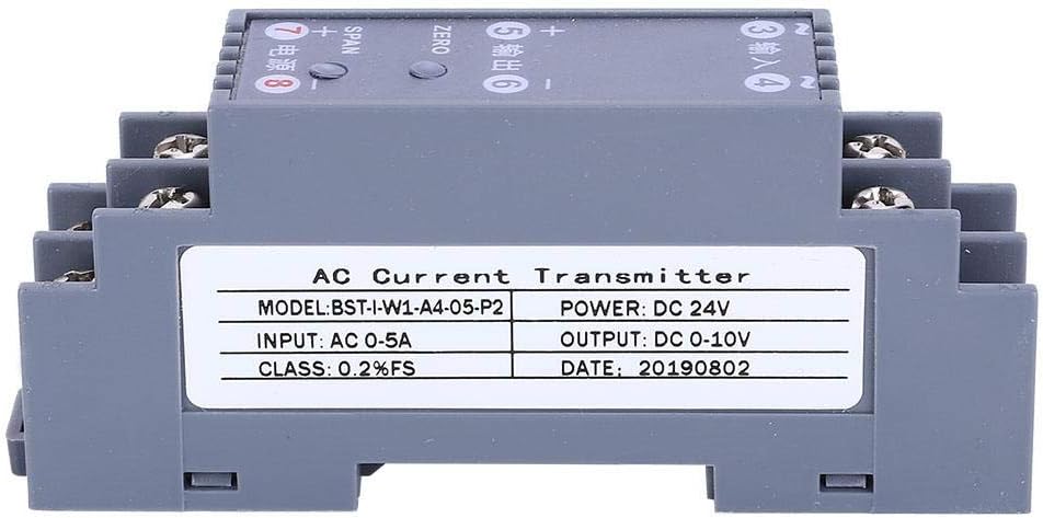
Figure 3.1: Thincol AC Current Transducer (Model: BST-I-W1-A4-O5-P2).
3.1. Description
The Thincol AC Current Transducer (Model: BST-I-W1-A4-O5-P2) is a high-precision signal transmitter housed in an ABS flame-retardant plastic shell. It features a one-in one-out channel configuration, converting AC 0-5A input to DC 0-10V output. Designed for reliability, it offers strong anti-interference ability and good stability, preventing instant waves. Its compact design supports standard DIN35MM rail installation.
3.2. Key Features
- High Precision: Supports 0.2% SF accuracy for reliable signal conversion.
- Fast Response: Quick response time of ≤100MS.
- Robust Design: ABS flame-retardant plastic shell with stainless steel terminal blocks for durability.
- Strong Anti-interference: Prevents instant waves, ensuring stable operation.
- Easy Installation: Compatible with international standard DIN35MM card slot guide rail installation.
- Wide Application: Ideal for electrical installations, automatic control, and dispatching systems in various industries.
3.3. Package Contents
- 1 x Thincol AC Current Transducer (Model: BST-I-W1-A4-O5-P2)
4. Specifications
| Parameter | Value |
|---|---|
| Model | BST-I-W1-A4-O5-P2 |
| Item Type | Transmitter |
| Channel Configuration | One-in one-out |
| Power Supply Voltage | DC 24V ± 10% |
| Rated Power Consumption | ≤1W |
| Response Time | ≤100MS |
| Insulation Strength | 2000V AC / 1 MIN |
| Insulation Resistance | ≥100MΩ |
| Ambient Temperature | -20°C to 55°C |
| Material | ABS flame retardant plastic |
| Accuracy | 0.2% SF |
| Input | AC 0-5A |
| Output | DC 0-10V |
| Installation | DIN35MM Rail Mount |

Figure 4.1: Product dimensions of the AC Current Transducer.
5. Setup and Installation
Follow these steps for proper installation of the AC Current Transducer:
- Mounting: The transducer is designed for DIN35MM rail installation. Securely clip the device onto a standard 35mm DIN rail in your electrical cabinet or control panel.
- Power Supply Connection: Connect the DC 24V power supply to terminals 7 (+) and 8 (-) as indicated on the device. Ensure the polarity is correct.
- AC Current Input Connection: Connect the AC current source (0-5A) to terminals 3 (Input) and 4 (Input). Ensure the input current is within the specified range.
- DC Voltage Output Connection: Connect your receiving device (e.g., PLC, display, data acquisition system) to terminals 5 (+) and 6 (-) for the DC 0-10V output. Observe correct polarity.
- Wiring Verification: Double-check all wiring connections for tightness and correct polarity before applying power. The stainless steel terminal blocks are designed for secure and fast wiring.

Figure 5.1: AC Current Transducer installed in a control panel with wiring connections.
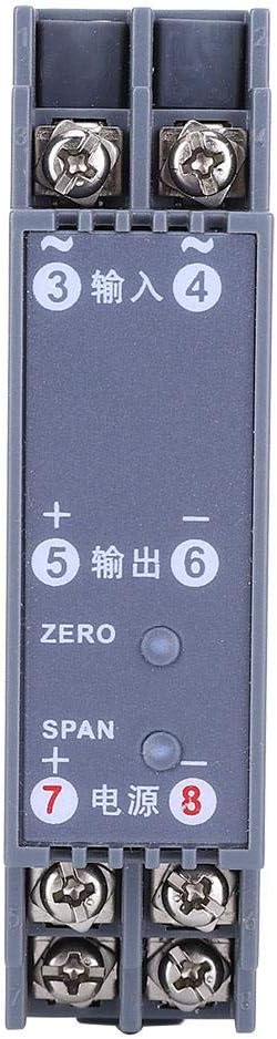
Figure 5.2: Top view of the transducer showing terminal connections and adjustment points.
6. Operating Instructions
Once the transducer is correctly installed and powered, it will begin converting the AC current input to a DC voltage output. Calibration may be required for precise measurements.
6.1. Initial Power-Up
After completing all wiring, apply DC 24V power to the device. The transducer will power on and begin processing the input signal.
6.2. Calibration (ZERO and SPAN Adjustment)
The transducer features ZERO and SPAN adjustment potentiometers to fine-tune the output signal. These are typically small screws accessible on the top of the unit.
- ZERO Adjustment: With no AC current input (0A), adjust the "ZERO" potentiometer until the DC output is 0V. This sets the lower limit of the output range.
- SPAN Adjustment: Apply a known maximum AC current input (e.g., 5A) to the device. Adjust the "SPAN" potentiometer until the DC output is 10V. This sets the upper limit of the output range.
- Repeat ZERO and SPAN adjustments as necessary for optimal accuracy.
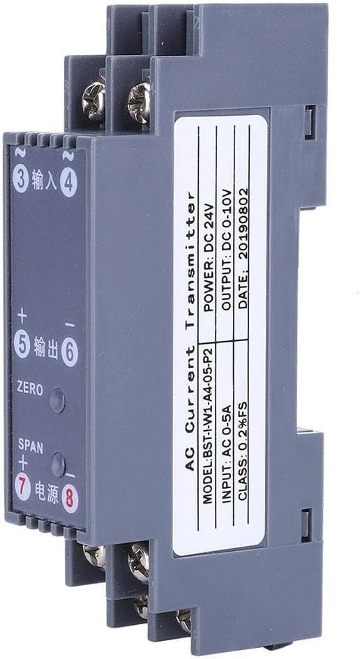
Figure 6.1: Side view highlighting ZERO and SPAN adjustment points.
7. Maintenance
The Thincol AC Current Transducer is designed for low maintenance. However, regular checks can ensure its longevity and reliable performance:
- Cleaning: Keep the device clean and free from dust and debris. Use a soft, dry cloth for cleaning. Do not use liquid cleaners or solvents.
- Connection Checks: Periodically inspect all wiring connections to ensure they remain tight and secure. Loose connections can lead to inaccurate readings or device malfunction.
- Environmental Conditions: Ensure the operating environment remains within the specified ambient temperature range (-20°C to 55°C) and is free from excessive humidity.
- Recalibration: If you suspect a drift in accuracy, perform the ZERO and SPAN calibration procedure as described in Section 6.2.
8. Troubleshooting
If you encounter issues with your AC Current Transducer, refer to the following common problems and solutions:
| Problem | Possible Cause | Solution |
|---|---|---|
| No output signal | No power supply; Incorrect wiring; Faulty input signal. | Verify DC 24V power supply is connected and active. Check all wiring connections for correctness and tightness. Ensure AC current input is present. |
| Inaccurate output reading | Needs calibration; Input current outside range; Interference. | Perform ZERO and SPAN calibration (Section 6.2). Confirm AC input current is within 0-5A. Check for strong electromagnetic interference sources nearby. |
| Unstable output signal | Loose connections; Electrical noise; Faulty unit. | Tighten all terminal connections. Ensure proper grounding. If problem persists, contact support. |
| Device not mounting securely on DIN rail | Incorrect DIN rail size; Damaged mounting clip. | Ensure you are using a standard 35mm DIN rail. Inspect the mounting clip for damage. |
If the problem persists after attempting these solutions, please contact Thincol customer support for further assistance.
9. Warranty and Support
Specific warranty information for the Thincol AC Current Transducer (Model: BST-I-W1-A4-O5-P2) was not provided with this product documentation. For details regarding warranty coverage, technical support, or service, please refer to the product packaging or contact Thincol directly through their official website or customer service channels.
Thincol Customer Support: Please visit the official Thincol website for contact information, FAQs, and additional resources.