1. Introduction
This manual provides comprehensive instructions for the installation, operation, and maintenance of the MSI B450 TOMAHAWK MAX II motherboard. Please read this manual thoroughly before proceeding with installation to ensure proper setup and optimal performance.
The MSI B450 TOMAHAWK MAX II is an ATX gaming motherboard based on the AMD B450 chipset, designed to support AMD processors with the AM4 socket. It features support for DDR4 memory, multiple storage options including M.2 and SATA, and various USB interfaces for connectivity.
2. Safety Information
Observe the following safety precautions to prevent damage to the motherboard and injury to yourself:
- Always disconnect the power cord from the wall outlet before touching any component inside the computer.
- Wear an anti-static wrist strap or frequently touch a grounded metal object (e.g., the computer case) to discharge static electricity before handling components.
- Handle the motherboard by its edges to avoid touching sensitive components.
- Keep the motherboard away from moisture and extreme temperatures.
- Ensure proper ventilation within the computer case to prevent overheating.
3. Setup and Installation
3.1 Package Contents
Verify that all items are present in the package. If any item is damaged or missing, contact your retailer.
- MSI B450 TOMAHAWK MAX II Motherboard
- SATA Cables
- I/O Shield
- User Manual and Quick Installation Guide
- Driver CD/DVD
- M.2 Screws

Figure 3.1: Contents of the MSI B450 TOMAHAWK MAX II Motherboard package, including the motherboard, cables, manual, and driver disc.
3.2 Motherboard Layout
Familiarize yourself with the various components and connectors on the motherboard.
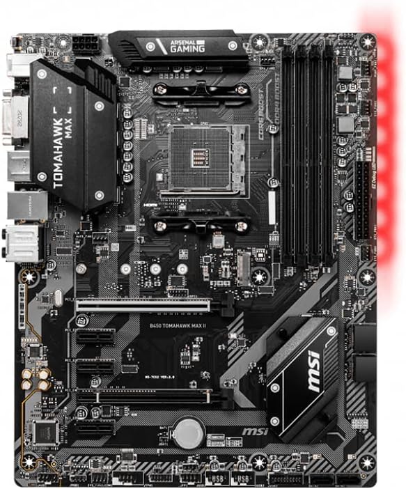
Figure 3.2: Top-down view of the MSI B450 TOMAHAWK MAX II Motherboard, highlighting the CPU socket, DIMM slots, PCIe slots, and various headers.

Figure 3.3: Rear I/O panel of the MSI B450 TOMAHAWK MAX II Motherboard, showing USB ports, HDMI, DVI-D, LAN, and audio jacks.
3.3 CPU Installation
- Open the CPU socket lever.
- Align the CPU with the socket, ensuring the golden triangle on the CPU matches the triangle on the socket.
- Gently place the CPU into the socket without forcing it.
- Close the CPU socket lever to secure the CPU.
- Apply thermal paste and install the CPU cooler according to its instructions.
3.4 Memory (RAM) Installation
- Open the clips at both ends of the DIMM slots.
- Align the notch on the DDR4 memory module with the key in the DIMM slot.
- Insert the memory module firmly into the slot until the clips snap into place.
- For dual-channel configuration, refer to the motherboard manual for recommended slot pairing.
3.5 Storage Device Installation (M.2 and SATA)
M.2 SSD Installation:
- Locate the M.2 slot on the motherboard.
- Remove the M.2 standoff screw.
- Insert the M.2 SSD into the slot at a 30-degree angle.
- Gently push down the M.2 SSD and secure it with the standoff screw.
SATA Drive Installation:
- Connect one end of the SATA data cable to a SATA port on the motherboard.
- Connect the other end of the SATA data cable to your SATA hard drive or SSD.
- Connect a SATA power cable from your power supply to the drive.
3.6 Graphics Card Installation
- Locate the primary PCIe 3.0 x16 slot.
- Open the retention clip at the end of the slot.
- Align the graphics card with the slot and press down firmly until it clicks into place.
- Secure the graphics card to the case with screws.
- Connect any necessary PCIe power cables from your power supply to the graphics card.
3.7 Power Supply Connections
- Connect the 24-pin ATX power connector from the power supply to the motherboard.
- Connect the 8-pin (or 4+4-pin) CPU power connector to the motherboard's CPU power header.
3.8 Front Panel Connections
Connect the cables from your computer case's front panel to the corresponding headers on the motherboard. These include:
- Power Switch (PWR_SW)
- Reset Switch (RESET_SW)
- HDD LED (HDD_LED)
- Power LED (PLED)
- Front Panel USB headers
- Front Panel Audio header
Refer to the detailed motherboard manual for exact pin configurations for each header.
3.9 Motherboard Mounting
- Install the I/O shield into the rear opening of your computer case.
- Ensure standoffs are correctly installed in your case, matching the motherboard's screw holes.
- Carefully place the motherboard into the case, aligning the screw holes with the standoffs and the I/O ports with the I/O shield.
- Secure the motherboard with screws. Do not overtighten.
4. Operating Instructions
4.1 First Boot and BIOS/UEFI Setup
- After assembling all components, connect your monitor, keyboard, and mouse.
- Connect the power cord to the power supply and turn on the power supply switch.
- Press the power button on your computer case.
- During the boot process, repeatedly press the Del key to enter the BIOS/UEFI setup utility.
- In the BIOS/UEFI, you can configure boot order, system time, and various hardware settings. Save changes before exiting.
4.2 Operating System Installation
Once the BIOS/UEFI is configured, you can proceed with installing your preferred operating system (e.g., Windows, Linux) from a USB drive or DVD.
4.3 Driver Installation
After operating system installation, install the necessary drivers for the motherboard's components (chipset, audio, LAN, etc.). These drivers are typically provided on the included driver CD/DVD or can be downloaded from the MSI website.
5. Maintenance
5.1 Cleaning
- Regularly clean dust from inside your computer case, especially from fans and heatsinks, using compressed air.
- Ensure the computer is powered off and unplugged before cleaning.
- Do not use liquid cleaners directly on motherboard components.
5.2 BIOS/UEFI Updates
Periodically check the MSI website for updated BIOS/UEFI versions. BIOS updates can improve system stability, add support for new CPUs, or fix bugs. Follow the instructions provided by MSI carefully when performing a BIOS update.
6. Troubleshooting
This section addresses common issues you might encounter.
| Problem | Possible Cause | Solution |
|---|---|---|
| No Power / System Does Not Turn On | Loose power connections, faulty power supply, incorrect front panel wiring. | Check all power cables (24-pin ATX, 8-pin CPU, GPU PCIe). Verify front panel power switch connection. Test power supply. |
| No Display / Black Screen | Graphics card not seated correctly, monitor cable disconnected, faulty RAM. | Reseat graphics card and RAM modules. Check monitor cable connection. Test with a different monitor or graphics card if possible. |
| System Freezes or Crashes | Overheating, unstable RAM, outdated drivers, corrupted OS. | Check CPU/GPU temperatures. Run memory diagnostic. Update drivers. Reinstall OS if necessary. |
| M.2 SSD Not Detected | Incorrect installation, BIOS settings, M.2 slot sharing SATA lanes. | Ensure M.2 SSD is properly seated and secured. Check BIOS settings for M.2 detection. Note that some M.2 slots share bandwidth with SATA ports, disabling certain SATA ports when an M.2 drive is used. Refer to the motherboard manual for details. |
For more detailed troubleshooting, consult the full user manual available on the MSI support website or contact MSI technical support.
7. Specifications
The following table outlines the key specifications for the MSI B450 TOMAHAWK MAX II Motherboard:
| Feature | Detail |
|---|---|
| Chipset | AMD B450 |
| CPU Socket | Socket AM4 |
| Supported Processors | AMD Ryzen Processors (1st, 2nd, 3rd Gen Ryzen / Ryzen with Radeon Vega Graphics and 2nd Gen Ryzen with Radeon Graphics / Athlon with Radeon Vega Graphics Desktop Processors for Socket AM4) |
| Memory | 4 x DDR4 DIMM slots, up to 64GB, supports DDR4 1866/ 2133/ 2400/ 2667Mhz (by JEDEC), 2667/ 2800/ 2933/ 3000/ 3066/ 3200/ 3466/ 3733/ 3866/ 4000/ 4133Mhz (by A-XMP OC MODE) |
| Expansion Slots | 1 x PCIe 3.0 x16 slot, 1 x PCIe 2.0 x16 slot (x4 mode), 3 x PCIe 2.0 x1 slots |
| Storage | 6 x SATA 6Gb/s ports, 1 x M.2 slot (supports PCIe 3.0 x4 and SATA 6Gb/s) |
| USB Ports | USB 3.2 Gen 2 (Type-A + Type-C), USB 3.2 Gen 1 (Type-A), USB 2.0 |
| Audio | Realtek ALC892 Codec, 7.1-Channel High Definition Audio |
| LAN | Realtek 8111H Gigabit LAN controller |
| Form Factor | ATX (12.0 in. x 9.6 in.) |
8. Warranty and Support
MSI products are covered by a limited warranty. The specific terms and duration of the warranty may vary by region and product type. Please retain your proof of purchase for warranty claims.
8.1 Technical Support
For technical assistance, driver downloads, BIOS updates, and FAQs, please visit the official MSI support website:
You may also contact MSI customer service directly through their website for further assistance.


