Introduction
This manual provides essential information for the safe and efficient operation of your Walfront YX851 Automatic Power Switch Module. Please read it thoroughly before installation and use. This module is designed to automatically switch between a primary power supply and a battery, ensuring continuous power to a load and managing battery charging.
Safety Information
- Ensure all power sources are disconnected before installation or maintenance.
- This module operates with DC 12V. Do not exceed specified voltage or current ratings.
- Installation should be performed by qualified personnel or individuals with sufficient electrical knowledge.
- Protect the module from moisture, dust, and extreme temperatures.
- Verify correct polarity for all connections to prevent damage to the module or connected devices.
- Keep out of reach of children.
Product Overview
The Walfront YX851 is an automatic power switch module designed for seamless power transition and battery management. It prioritizes a primary power supply and switches to a backup battery when the primary fails, while also handling battery charging.
Key Features
- Automatic power switching between main supply and battery.
- Integrated battery charging control.
- Over-voltage and under-voltage charging protection for the battery.
- Compact plastic construction.
Components

The module features screw terminals for easy connection of power input, battery, and load. Two relays manage the power switching logic. Indicator lights (not explicitly visible in this image but implied by "power indicator light" in the description) provide status feedback.
- Input Terminals: For connecting the primary power supply.
- Battery Terminals: For connecting the backup battery.
- Load Terminals: For connecting the device requiring power.
- Relays: Two blue relays (SRD-12VDC-SL-C) rated for 10A 250VAC / 10A 125VAC / 10A 30VDC / 10A 28VDC.
- Potentiometers (W 203): Used for adjusting charging start and stop voltages.
- Indicator Lights: (Implied) for power and charging status.
Specifications
| Parameter | Value |
|---|---|
| Model | YX851 |
| Control Voltage | DC 12V |
| Control Current | 10A |
| Material | Plastic |
| Dimensions (LxWxH) | Approx. 69 x 48 x 18mm (2.7 x 1.9 x 0.7in) |
| Mounting Size | Approx. 61 x 41mm (2.4 x 1.6in) |
| Relay Rating | 10A 250VAC / 10A 125VAC / 10A 30VDC / 10A 28VDC |
Setup and Installation
Proper installation is critical for the correct functioning of the YX851 module. Refer to the wiring diagram below for connections.
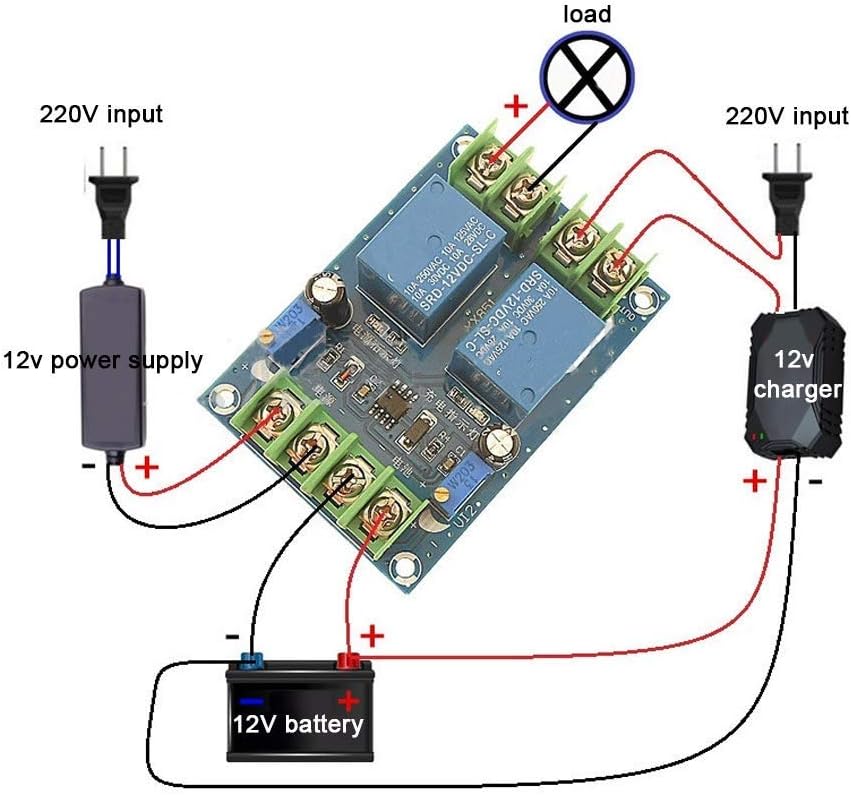
The diagram shows a typical setup where a 220V input is converted to 12V for the primary supply. A separate 12V charger is connected to the battery, and the module manages the power flow to the load.
Wiring Steps
- Connect Primary Power Supply: Connect your DC 12V primary power supply to the "IN" terminals on the module, observing polarity (+ to + and - to -). Ensure the primary power supply is capable of providing sufficient current for both the load and battery charging.
- Connect Battery: Connect your 12V backup battery to the "BATTERY" terminals, observing polarity.
- Connect Load: Connect your DC 12V load to the "OUT" terminals, observing polarity.
- Verify Connections: Double-check all wiring for correct polarity and secure connections before applying power.
Adjusting Charging Parameters
The module features two potentiometers (W 203) for adjusting the battery charging start and stop voltages.
- Charging Start Voltage Regulation: Adjust the potentiometer labeled for "charging start" (often near "充电启动" on the PCB, see Figure 3). Turning clockwise increases the voltage at which charging begins; turning counter-clockwise decreases it.
- Charging Stop Voltage Regulation: Adjust the potentiometer labeled for "charging stop" (often near "充电关闭" on the PCB, see Figure 3). Turning clockwise increases the voltage at which charging stops; turning counter-clockwise decreases it.
It is recommended to use a voltmeter to accurately set these thresholds according to your battery's specifications.

The bottom of the PCB provides labels for identifying the charging start and stop points, which correspond to the adjustable potentiometers on the top side.
Operating Instructions
The YX851 module operates automatically based on the presence and voltage levels of the primary power supply and the connected battery.
- Primary Power Available: When the primary DC 12V power supply is connected and active, the module will prioritize this supply to power the load.
- Battery Charging: If the primary power supply is active and the battery voltage is below the set charging stop voltage, the module will initiate charging of the battery. Charging will continue until the battery reaches the set charging stop voltage.
- Primary Power Failure: If the primary power supply fails or its voltage drops below a critical threshold, the module will automatically switch the load to be powered by the connected 12V battery. This ensures uninterrupted operation for the load.
- Primary Power Restoration: When the primary power supply is restored, the module will automatically switch the load back to the primary supply and resume battery charging if needed.
The module's indicator lights (if present) will provide visual feedback on the current power source and charging status.
Maintenance
- Regularly inspect all wiring connections to ensure they are secure and free from corrosion.
- Keep the module clean and free from dust and debris. Use a soft, dry cloth for cleaning.
- Avoid exposing the module to excessive heat, cold, or moisture.
- Periodically check the battery voltage to ensure it is within healthy operating parameters.
- Do not attempt to open the module casing or modify its internal components, as this may void any potential warranty and could lead to damage or injury.
Troubleshooting
| Problem | Possible Cause | Solution |
|---|---|---|
| Load not receiving power | No primary power; Battery discharged; Incorrect wiring; Faulty module. | Check primary power supply; Check battery charge level; Verify all wiring connections and polarity; Contact support if module is suspected faulty. |
| Battery not charging | Primary power supply off or insufficient; Battery already full (above stop voltage); Incorrect charging voltage settings; Faulty battery. | Ensure primary power is active and sufficient; Adjust charging start/stop voltages; Test battery independently. |
| Module not switching automatically | Incorrect wiring; Primary power supply fluctuating; Module fault. | Re-check wiring diagram; Ensure stable primary power; Contact support. |
| Overheating | Overload on output; Insufficient ventilation; Short circuit. | Reduce load; Ensure adequate airflow around module; Check for short circuits in wiring or load. |
Warranty and Support
For technical assistance or inquiries regarding your Walfront YX851 Automatic Power Switch Module, please contact Walfront customer support. Refer to your purchase documentation for specific warranty terms and conditions.
You can visit the Walfront store for more information: Walfront Store on Amazon.
