1. Introduction
This manual provides comprehensive instructions for the installation, operation, and maintenance of the DALY BMS 4S 12V 250A LiFePO4 Battery Protection Module. It is designed to ensure optimal performance and longevity of your lithium battery pack. Please read this manual thoroughly before installation and use.
The DALY BMS is engineered to maximize and optimize lithium battery performance, significantly extending battery lifetime. It incorporates advanced protection features and robust construction for reliable operation.
2. Product Features
- Comprehensive Protection: Includes overcurrent, overcharge, overdischarge, short circuit, and temperature protection.
- Enhanced Durability: Features double protection with injection patent technology and a patent shell, providing waterproof, dustproof, shockproof, and anti-static properties.
- High-Quality Components: Constructed with pressure-resistant and durable materials, ensuring high acquisition accuracy.
- Ease of Connection: Designed for easy plug-and-unplug functionality, simplifying the electrical connection between the battery pack and the BMS.
- Integrated Indicator Light: Provides visual feedback on working conditions.

Figure 1: Overview of DALY BMS key features.
3. Specifications
| Specification | Value |
|---|---|
| Product Dimensions | 4.72 x 9.25 x 2.05 inches |
| Item Weight | 3.31 pounds (1500 Grams) |
| Model Number | DALY-LiFePO4-250AFAN |
| Input Voltage | 3.75 Volts (per cell, for 4S 12V system) |
| Discharge Current | 250A |
| Overdischarge Current | 375 ± 3A |
| Charging Current | 250A |
| Overcharge Current | 375 ± 3A |
| Overcharge Voltage | 3.75V ± 0.05V (adjustable) |
| Overdischarge Voltage | 2.2V ± 0.05V (adjustable) |
| Charge Voltage | 14.6V |
| Manufacturer | Dongguan Daly Electronics Co., Ltd |
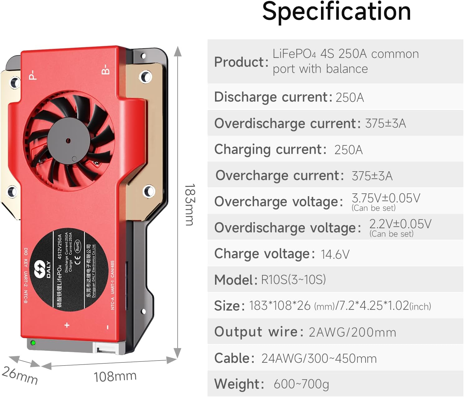
Figure 2: Detailed product specifications and dimensions.
4. Installation and Wiring
Proper installation and wiring are crucial for the safe and effective operation of your DALY BMS. Follow these steps carefully.
4.1. Prepare Materials
Before starting, ensure you have all necessary tools and components:
- DALY BMS unit
- NTC sensor
- Sampling cable (balance leads)
- Multimeter
- Soldering iron and solder
- Ceramic scissors (insulated)
- Double-sided adhesive tape
Video 1: Guide on preparing materials for DALY BMS wiring.
4.2. Sampling Point Determination
Accurately identify the sampling points on your battery pack. This involves determining the order of string numbers and verifying voltages with a multimeter.
Video 2: Detailed instructions for determining DALY BMS sampling points.
4.3. Wiring Steps
Follow these steps for connecting the balance leads to your battery pack:
- Solder the sampling cables: Connect the black cable (B0) to the negative terminal of the battery pack. Then, connect the red cables (B1, B2, B3, etc.) sequentially to the positive terminals of each cell string, starting from the first string.
- Check the cables: After connecting the cables, measure the voltage between two adjacent cables starting from the header to ensure there are no wrong connections or missing connections.
- Connect the output wires: Connect the B- wire of the BMS to the total negative terminal of the battery pack, and then plug the sampling cable to the BMS.
- Activate the BMS: After activating the BMS, make sure that the voltage (battery voltage) between B+ & B- and the voltage between P+ & P- are consistent.

Figure 3: Standard wiring diagram for DALY BMS.
Video 3: Step-by-step guide for soldering DALY BMS wires.
5. Operating Instructions
The DALY BMS operates automatically to protect your battery pack. For standard BMS models, there are no communication functions. If you require smart BMS features, an active balancer, parallel module, or other accessories, please contact customer service.
5.1. Smart BMS App (If applicable)
For Smart BMS models (not standard), an accompanying app allows you to view and set various battery parameters. This app supports iOS and Android systems, multiple languages, and local remote monitoring (Bluetooth or WiFi module required).

Figure 4: DALY Smart BMS App interface for monitoring battery parameters.
6. Safety Precautions
- Always ensure correct wiring. Incorrect connections can damage the BMS or battery.
- Do not insert the BMS into the battery pack before completing and verifying all wiring connections.
- Avoid virtual welding or loose connections, as this can lead to voltage imbalances and potential damage.
- Use insulated tools when working with battery components.
- If you are a novice, it is recommended to set the soldering iron temperature to about 350 degrees Celsius to prevent damage.
7. Troubleshooting
This section addresses common issues that may arise during installation or operation.
7.1. Common Wiring Errors
Incorrect wiring can lead to various problems, including:
- Incorrect Wiring Harness: Using a wiring harness from a different manufacturer or an incompatible model can cause socket shedding or poor contact.
- Inserting BMS Prematurely: Inserting the BMS before all wires are correctly welded and verified can lead to internal component breakdown, preventing charging or discharging.
- Virtual Welding: Poor soldering can result in unstable connections, leading to voltage issues and potential damage.
- Incorrect P- and B- Line Connection: Improper connection of the main discharge/charge lines can cause short circuits, burning out sampling lines, or damaging the entire protective plate.
Video 4: Explanation of 5 common wiring errors to avoid during DALY BMS installation.
8. Warranty and Support
DALY BMS products come with a quality guarantee, including ISO/FCC/RoHS/PSE/CE approvals. For any technical assistance or support, please contact DALY customer service. We offer 24-hour one-on-one customer service and lifetime technical support.


