1. Introduction
This manual provides detailed instructions for the installation, operation, and maintenance of your Sonew DC12V/24V Electric Bolt Lock. Please read this manual thoroughly before installation and use to ensure proper function and safety. This electric bolt lock is designed for various door types, including wood, metal, and fire doors, offering secure access control.
2. Safety Information
- Electrical Safety: Ensure power is disconnected before performing any wiring or installation procedures. Incorrect wiring can cause damage to the device or pose an electrical hazard.
- Voltage Compatibility: This lock operates on DC12V or DC24V. Verify your power supply matches the lock's requirements.
- Professional Installation: For optimal safety and performance, professional installation is recommended.
- Environmental Conditions: Avoid exposing the lock to extreme temperatures, humidity, or corrosive environments.
- Authorized Personnel: Only authorized personnel should attempt to service or repair the lock.
3. Product Overview
3.1 Features
- Durable Construction: Lock body constructed from aluminum alloy, designed for stability and resistance to impact.
- Anti-Dismantling Design: Utilizes hexagonal screws for secure installation, preventing unauthorized removal without specific tools.
- Adjustable Delay Function: Features a selectable delay for unlocking (0, 3, or 6 seconds), which can extend the bolt's lifespan.
- Dual Voltage Compatibility: Supports both DC12V and DC24V power inputs.
- Fail-Secure Operation: The lock is designed to lock when power is applied and unlock when power is removed (power-on lock, power-off unlock).
- Low Power Consumption: Efficient design minimizes power usage.
- Versatile Application: Suitable for wooden, metal, fire, and glass doors in various settings such as homes, offices, and commercial spaces.
3.2 Components
The Sonew Electric Bolt Lock package includes the following components:
- Electric Bolt Lock Body
- Accessory Body (Strike Plate)
- Mounting Screw Pack
- Instruction Manual (this document)

Image: Overview of the Sonew Electric Bolt Lock and its accessory body, typically used as a strike plate. The lock features a serial number label and voltage/current specifications.

Image: The Sonew Electric Bolt Lock units shown with the included mounting screws. This illustrates the complete set of hardware provided for installation.
4. Specifications
| Specification | Value |
|---|---|
| Brand | Sonew |
| Model Number | 390f00fc-d57d-4ffe-8618-af9135f6106a |
| Material | Aluminum Alloy |
| Operating Voltage | DC12V/24V ±0.5 |
| Current | 150mA |
| Delay Adjustment | 0, 3, 6 seconds |
| Lock Type | Power-on lock, Power-off unlock (Fail-Secure) |
| Wiring | 4-wire cable connection |
| Item Weight | 1.13 pounds (approx. 0.51 kg) |
| Package Dimensions | 7.6 x 4.72 x 1.89 inches (approx. 19.3 x 12 x 4.8 cm) |
| Recommended Uses | Homes, Offices, Commercial Buildings, Storage Units |
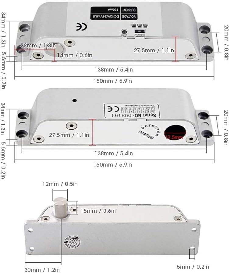
Image: Detailed dimensions of the Sonew Electric Bolt Lock, showing length, width, height, and bolt protrusion measurements in both millimeters and inches.
5. Installation
Proper installation is crucial for the security and functionality of the electric bolt lock. Follow these steps carefully.
- Prepare the Door and Frame:
- Identify the desired mounting location on the door frame and the corresponding position on the door.
- Ensure sufficient space for the lock body and strike plate. Refer to the dimension diagram in Section 4.
- Mount the Lock Body:
- Drill pilot holes for the lock body on the door frame.
- Secure the electric bolt lock body using the provided hexagonal mounting screws. Ensure it is firmly attached and aligned correctly.

Image: The electric bolt lock installed on a door frame, showing the wiring connection and the alignment with the door.
- Mount the Accessory Body (Strike Plate):
- Align the accessory body (strike plate) with the bolt on the lock body when the door is closed.
- Mark and drill pilot holes on the door for the strike plate.
- Secure the strike plate using the provided screws.

Image: The electric bolt lock and its corresponding strike plate installed on a door, demonstrating how the two components align for secure locking.
- Wiring Connection:
- The lock uses a 4-wire cable connection. Refer to the wiring diagram (if provided separately or on the device label) for specific connections.
- Connect the wires to your access control system or power supply (DC12V/24V).
- Ensure all connections are secure and insulated to prevent short circuits.

Image: Close-up view of the electric bolt lock showing the 4-wire cable connection point, indicating where power and control signals are connected.
- Test Functionality:
- After installation and wiring, apply power and test the lock's operation.
- Verify that the bolt extends when power is applied and retracts when power is removed.
- Check for smooth operation and proper alignment.

Image: An example of the electric bolt lock installed on a glass door, demonstrating its application in various door types.
6. Operating Instructions
The Sonew Electric Bolt Lock operates as a fail-secure device, meaning it locks when power is supplied and unlocks when power is removed.
- Locking: When power (DC12V/24V) is supplied to the lock, the bolt will extend, securing the door.
- Unlocking: When the power supply to the lock is interrupted (e.g., via an access control system, button, or power failure), the bolt will retract, allowing the door to open.
- Delay Adjustment: The lock features a delay setting for unlocking. This can be adjusted to 0, 3, or 6 seconds using the switch located on the lock body. Adjusting this delay can help prevent rapid cycling and extend the life of the bolt mechanism.

Image: A close-up of the electric bolt lock showing the indicator light and the switch for adjusting the delay time (0, 3, or 6 seconds) for unlocking.
7. Maintenance
Regular maintenance ensures the longevity and reliable operation of your electric bolt lock.
- Cleaning: Periodically wipe the lock body with a soft, dry cloth. Avoid using abrasive cleaners or solvents.
- Inspection: Regularly inspect the lock for any signs of wear, damage, or loose connections.
- Alignment: Ensure the lock bolt and strike plate remain properly aligned. Misalignment can cause excessive wear or prevent proper locking.
- Lubrication: Do not lubricate the internal mechanisms unless specifically instructed by the manufacturer.
8. Troubleshooting
If you encounter issues with your electric bolt lock, refer to the following common problems and solutions.
| Problem | Possible Cause | Solution |
|---|---|---|
| Lock does not engage (bolt does not extend) | No power supply; Incorrect wiring; Faulty power supply; Lock malfunction. | Check power connections and voltage; Verify wiring against diagram; Test power supply; Contact support if lock is faulty. |
| Lock does not disengage (bolt does not retract) | Constant power supply; Incorrect wiring; Mechanical obstruction; Lock malfunction. | Ensure power is cut off for unlocking; Verify wiring; Check for obstructions in the bolt path; Contact support. |
| Bolt operates sluggishly or with difficulty | Misalignment between lock and strike plate; Dirt or debris in mechanism; Low voltage. | Adjust alignment; Clean the bolt and strike plate area; Verify correct voltage supply. |
| Indicator light not working | No power; Faulty indicator light. | Check power supply; The lock may still function even if the light is faulty. |
9. Warranty and Support
This Sonew Electric Bolt Lock is designed for durability and reliable performance. For specific warranty information, please refer to the documentation provided at the time of purchase or contact Sonew customer support.
If you require technical assistance or have questions not covered in this manual, please visit the official Sonew website or contact their customer service department. When contacting support, please have your product model number (390f00fc-d57d-4ffe-8618-af9135f6106a) and purchase details available.
Sonew Official Store: Visit the Sonew Store on Amazon


