1. Overview
The DALY BMS (Battery Management System) 24S 72V 120A LiFePO4 Battery Protection Module is designed to safeguard your 18650 LiFePO4 battery pack. It provides essential protection against overcurrent, overcharge, overdischarge, short circuits, and temperature fluctuations, thereby optimizing battery performance and extending its lifespan. This standard BMS model includes a cooling fan for enhanced thermal management.
Key Features:
- Comprehensive Protection: Guards against overcurrent, overcharge, overdischarge, short circuit, and temperature issues.
- Enhanced Durability: Features double protection through injection patent technology and a patent shell, offering waterproof, dustproof, shockproof, and anti-static properties.
- High-Quality Components: Constructed with pressure-resistant and durable materials, ensuring high acquisition accuracy.
- Integrated Cooling Fan: Maintains optimal operating temperatures for the BMS.
Package Contents:
- 3.2V LiFePO4 BMS (1 unit)
- NTC Sensor (1 unit)
- Sampling Cable (1 unit)
- Instruction Manual (1 unit)
2. Safety Information
Always prioritize safety when working with battery management systems and high-voltage battery packs. Failure to follow safety guidelines can result in serious injury, property damage, or product malfunction.
- Professional Installation Recommended: Installation should ideally be performed by qualified personnel with experience in battery systems.
- Insulated Tools: Use insulated tools to prevent accidental short circuits.
- Disconnect Power: Always disconnect the battery pack from any power sources before installation or maintenance.
- Correct Polarity: Ensure all connections adhere to correct polarity to avoid damage to the BMS and battery.
- Avoid Short Circuits: Take extreme care to prevent short circuits during wiring and operation.
- Ventilation: Ensure adequate ventilation around the battery pack and BMS.
- Protective Gear: Wear appropriate personal protective equipment (PPE), such as insulated gloves and eye protection.
3. Product Features & Components
The DALY BMS is engineered for robust performance and reliability. Below are visual representations and descriptions of its key features and internal structure.

Figure 1: Top view of the DALY BMS 24S 72V 120A LiFePO4 Battery Protection Module, showing the DALY logo and BMS-120A label.

Figure 2: Side view of the DALY BMS, highlighting the cooling fan and connection terminals.
Internal Structure:
The BMS features a multi-layered design for optimal protection and heat dissipation.

Figure 3: Exploded view illustrating the internal components of the DALY BMS, including the insulated flame-retardant shell, smart cooling fan, pure aluminum heat sinks, high current copper plate, DALY BMS control board, thermal conductive compound, and insulation fixing plate.
Video 1: DALY BMS 80A-500A with Cooling Fan Introduction. This video provides a visual overview of the BMS models with cooling fans and highlights their robust construction and features.
Fan Specifications:
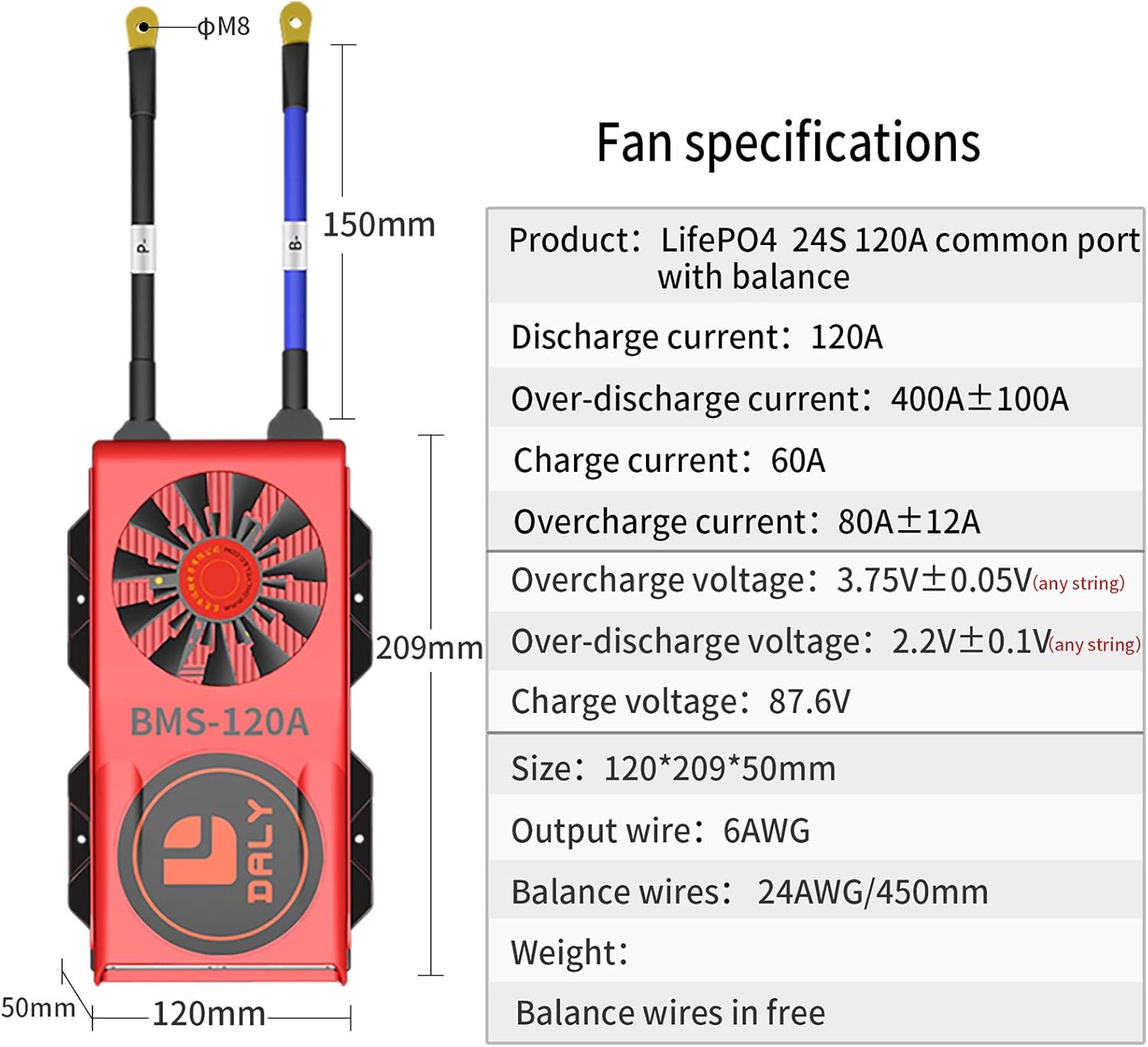
Figure 4: Table detailing the fan specifications for the LiFePO4 24S 120A common port BMS with balance, including discharge current, over-discharge current, charge current, overcharge current, overcharge voltage, over-discharge voltage, charge voltage, size, output wire gauge, balance wire gauge, and weight.
4. Installation & Wiring
Proper installation and wiring are critical for the safe and effective operation of your DALY BMS. Follow these steps carefully.
4.1 Preparing Materials and Tools:
Before beginning the wiring process, ensure you have the following tools and materials:
- Soldering machine (suggested temperature: 662°F/350°C; for novices, about 350°C)
- Ceramic scissors (insulated, for cutting wires)
- Multimeter (for checking voltages)
- Detection board (for verifying wiring accuracy)
- Double-sided tape
- Tin wire
Video 2: Prepare materials before Daly BMS wiring. This video demonstrates the necessary tools and materials for wiring your DALY BMS.
4.2 Sampling Point Determination:
Accurately identifying sampling points on your battery pack is crucial for correct BMS operation.
Video 3: Daly BMS sampling point determination. This video guides you through the process of identifying and marking the correct sampling points on your battery pack using a multimeter.
4.3 Wiring Instructions:
Follow these steps for proper wiring of the BMS to your battery pack:
- After assembling your LiFePO4 battery pack, mark battery B-, B1, B2, ..., until battery pack B+.
- Fix balance wires on the battery pack where black wire can reach battery pack B-. The 1st red wire can reach B1, 2nd red wire can reach B2, ..., until the last red wire can reach battery pack B+ with double-sided tape.
- Cut off excess length with scissors, welding the black wire's end at Battery pack B-, welding the 1st red wire's end at B1, 2nd red wire's end at B2, ..., until the last red wire's end at Battery pack B+.
- Measure balance wire ends' 2 neighboring metal points voltage. If the voltage range is 2.0V-3.6V, that means wiring is correct.
- Connect balance wires white end with BMS connection port, use multimeter ohm detection function and turn on the buzzer. Connect multimeter's black test pen with BMS P- and multimeter's red test pen with BMS B-. When there is a beep sound, the BMS circuit conduction is OK and continuous.
- Use multimeter DC voltage function to measure battery pack's voltage (between Battery B- and Battery B+) and through BMS output voltage (between BMS B- and Battery B+). If they are the same voltage, the BMS can work normally already and fix BMS to avoid poor contact due to severe vibration during use.

Figure 5: Detailed wiring diagram for the DALY BMS, illustrating connections to the battery pack, motor/load, and charger.
Video 4: Daly BMS Wires Soldering Video. This video demonstrates the correct soldering technique for connecting the balance wires to the battery pack.
4.4 Common Wiring Errors to Avoid:
Understanding common mistakes can prevent damage and ensure proper functionality.
Video 5: Daly BMS Wiring 5 Common Errors Video. This video highlights frequent mistakes made during BMS wiring and explains how to avoid them, covering issues like incorrect wire usage, improper BMS insertion, virtual welding, and incorrect P- and B- line connections.
5. Operation
This DALY BMS is a standard model, primarily providing essential battery protection functions. It operates automatically to monitor and protect the battery pack based on its programmed parameters.
- Automatic Protection: The BMS automatically engages protection features (overcharge, overdischarge, overcurrent, short circuit, temperature) when thresholds are met.
- No Communication Functions: This standard BMS does not include communication features such as Bluetooth, UART, RS485, CAN, LCD, or GPS.
- Smart BMS Models: If advanced communication functions or active balancing are required, please consider DALY Smart BMS models. Contact customer service for more information on these variants.
6. Maintenance
Regular maintenance helps ensure the longevity and reliable performance of your DALY BMS and battery pack.
- Regular Inspection: Periodically inspect the BMS and all wiring for any signs of damage, loose connections, or corrosion.
- Cleanliness: Keep the BMS and surrounding area clean and free from dust and debris. Use a dry, soft cloth for cleaning.
- Temperature Management: Ensure the cooling fan is unobstructed and functioning correctly. Avoid operating the battery pack and BMS in extreme temperatures.
- Avoid Physical Damage: Protect the BMS from physical impact or excessive vibration.
7. Troubleshooting
If you encounter issues with your DALY BMS, refer to the common errors video and these general troubleshooting steps.
Common Issues and Solutions:
- No Power Output/Charging:
- Verify all wiring connections are secure and correct, especially the B- and P- lines.
- Check individual cell voltages with a multimeter to ensure no cells are critically over-discharged or damaged.
- Ensure the BMS is correctly inserted into the balance port after all wiring is complete.
- BMS Overheating:
- Check for proper ventilation around the BMS.
- Ensure the cooling fan is operational and not obstructed.
- Verify that the load current does not exceed the BMS's rated continuous discharge current.
- Battery Imbalance:
- Confirm that all balance wires are correctly connected to their respective cell taps.
- Measure the voltage between adjacent balance wire ends to ensure they are within the expected range (2.0V-3.6V for LiFePO4).
For complex issues or if troubleshooting steps do not resolve the problem, please contact DALY customer service for assistance.
8. Specifications
| Specification | Value |
|---|---|
| Product Dimensions | 8.23 x 4.72 x 1.97 inches |
| Item Weight | 3.7 pounds |
| Input Voltage | 72 Volts (DC) |
| Output Voltage | 72 Volts (DC) |
| Manufacturer | Dongguan Daly Electronics Co., Ltd |
| Certifications | ISO/ FCC/ RoHS/ PSE/ CE APPROVED |
9. Warranty & Support
DALY is committed to providing excellent customer service and support for its products.
- Customer Service: We offer 24-hour one-on-one customer service to assist with any inquiries or issues.
- Technical Support: Lifetime technical support is provided for all DALY BMS products.
- Contact Information: For customized BMS solutions, bulk orders, or technical assistance, please feel free to contact DALY customer service.


