
1. Introduction
This manual provides essential information for the safe and efficient installation, operation, and maintenance of your RATTMMOTOR 1.5kW 220V ER16 Air-Cooled Spindle Motor and VFD Kit. Please read these instructions thoroughly before use and retain them for future reference.
Package Contents:
- 1.5 kW CNC ER16 Air-Cooled Spindle Motor
- 1.5 kW 220V Variable Frequency Drive (VFD) Inverter
- 80mm Clamp Bracket

Figure 1.1: Complete RATTMMOTOR 1.5kW Spindle Motor and VFD Kit components.
2. Safety Information
Always observe the following safety precautions to prevent injury and damage to the equipment. This equipment involves high voltage and rotating parts.
- Electrical Safety: Ensure all wiring is performed by a qualified electrician. Disconnect power before any installation, maintenance, or troubleshooting.
- Personal Protective Equipment (PPE): Always wear appropriate PPE, including safety glasses, gloves, and hearing protection, when operating or working near the spindle motor.
- Rotating Parts: Keep hands, clothing, and tools clear of the spindle motor during operation. Never attempt to stop the spindle by hand.
- Ventilation: Ensure adequate ventilation for the VFD and spindle motor to prevent overheating.
- Emergency Stop: Implement an accessible emergency stop mechanism in your CNC system.
- Minimum Speed: The spindle rotation speed should not be lower than 9000 RPM during operation to ensure proper cooling and bearing longevity.
3. Product Overview
3.1 Spindle Motor
The 1.5kW air-cooled spindle motor is designed for high-speed milling and engraving applications. It features an ER16 collet for tool holding and operates at 220V AC.

Figure 3.1: RATTMMOTOR 1.5kW Air-Cooled Spindle Motor with electrical connector.
3.2 Variable Frequency Drive (VFD)
The 1.5kW VFD inverter controls the speed and direction of the spindle motor. It converts single or three-phase 220V input into variable frequency three-phase output for precise motor control.

Figure 3.2: RATTMMOTOR 1.5kW VFD showing control panel and internal view.
3.3 Clamp Bracket
The 80mm cast aluminum clamp bracket securely mounts the spindle motor to your CNC machine frame.

Figure 3.3: RATTMMOTOR 80mm Cast Aluminum Clamp Bracket.
4. Specifications
4.1 Spindle Motor Specifications
| Parameter | Value |
|---|---|
| Model | 1.5KW Air Cooled |
| Voltage | 220V |
| Power | 1.5 kW |
| Current | 6A |
| Frequency | 0-400 Hz |
| Rotation Speed | 0-24000 RPM |
| Collet Size | ER16 |
| Precision | 0.003-0.005 mm |
| Runout | Less than 0.05 mm |
| Diameter | 80 mm |
| Cooling | Air-cooled |
| Bearings | 4 bearings (C7004x2 + C7002x2), P4 class, Angular contact bearings |
| Bearing Lubrication | Grease |
| Material | Stainless Steel |
| Net Weight | 4.8 kg |
| Main Application | Wood, Aluminum, Stone, metal, glass, PVC industry |

Figure 4.1: Detailed technical specifications for the spindle motor.
4.2 VFD Inverter Specifications
| Parameter | Value |
|---|---|
| Power | 1.5 kW |
| Current | 7A |
| Input Voltage | 220V (+/- 15%) |
| Output Voltage | 0-220V |
| Input Frequency | 48-63 Hz |
| Output Frequency | 0-400 Hz |
| Input Phase | 1 or 3 phases |
| Output Phase | 3 phases |
4.3 Dimensional Drawings

Figure 4.2: Spindle Motor dimensional drawing.
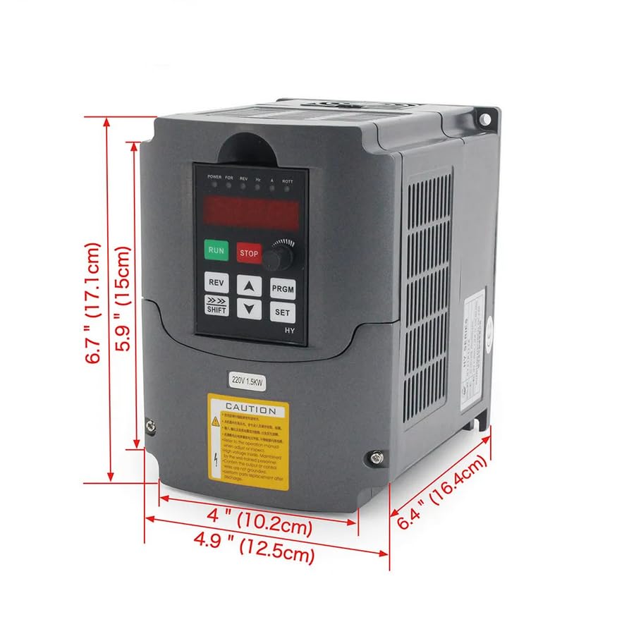
Figure 4.3: VFD Inverter dimensional drawing.
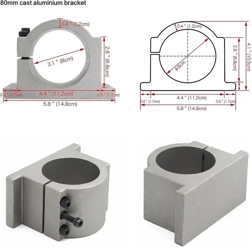
Figure 4.4: Clamp Bracket dimensional drawing.
5. Installation and Setup
5.1 Mounting the Spindle Motor
- Secure the 80mm clamp bracket to your CNC machine's Z-axis carriage using appropriate fasteners. Ensure the mounting surface is flat and rigid.
- Insert the spindle motor into the clamp bracket. Ensure it is seated firmly and aligned correctly.
- Tighten the clamp bracket screws evenly to secure the spindle motor. Do not overtighten, as this can damage the spindle housing.
5.2 VFD Wiring
WARNING: All electrical wiring must be performed by a qualified professional. Incorrect wiring can lead to severe injury or equipment damage.
- Input Power: Connect the 220V AC input power to the VFD's input terminals (typically R, S, T for 3-phase or L, N for 1-phase, refer to VFD manual for exact terminals). Ensure proper grounding.
- Spindle Motor Connection: Connect the three-phase output from the VFD (U, V, W) to the corresponding terminals on the spindle motor. Ensure the motor's ground wire is connected to the VFD's ground terminal.
- Control Wiring (Optional): If using external control signals (e.g., 0-10V for speed control, Run/Stop signals from a CNC controller), connect these to the VFD's control terminals as per the VFD's specific manual.
5.3 VFD Parameter Settings
The VFD requires specific parameter settings to match the spindle motor. Refer to the VFD's dedicated instruction manual for detailed programming steps. Key parameters to configure typically include:
- Motor Rated Power: 1.5 kW
- Motor Rated Voltage: 220V
- Motor Rated Current: 6A
- Motor Rated Frequency: 400 Hz
- Maximum Output Frequency: 400 Hz
- Acceleration/Deceleration Times: Adjust as needed for smooth operation.
6. Operation
After successful installation and VFD parameter configuration, the spindle motor is ready for operation.
- Power On: Apply power to the VFD. The VFD display should illuminate.
- Start Spindle: Use the VFD's RUN button or external control signal to start the spindle.
- Adjust Speed: Adjust the output frequency on the VFD to control the spindle speed. The spindle speed should not be lower than 9000 RPM during operation.
- Monitor Operation: Observe the spindle for unusual noises, vibrations, or excessive heat. If any abnormalities occur, stop the spindle immediately.
- Stop Spindle: Use the VFD's STOP button or external control signal to stop the spindle. Allow the spindle to come to a complete stop naturally.
6.1 Tool Changing (ER16 Collet)
- Ensure the spindle is completely stopped and power is disconnected.
- Use the appropriate wrench to loosen the ER16 collet nut.
- Remove the old tool and insert the new tool into the collet. Ensure the tool shank is clean and fully seated.
- Tighten the ER16 collet nut firmly with the wrench. Do not overtighten.
7. Maintenance
Regular maintenance ensures the longevity and optimal performance of your spindle motor and VFD.
- Cleaning: Regularly clean the exterior of the spindle motor and VFD to prevent dust and debris buildup, especially around cooling fins and vents. Use compressed air for the VFD's cooling fan.
- Bearing Check: Listen for unusual noises from the spindle bearings during operation. Increased noise or vibration may indicate bearing wear.
- Collet Inspection: Inspect the ER16 collet and collet nut for wear or damage. Replace if necessary to ensure proper tool gripping.
- Wiring Inspection: Periodically check all electrical connections for tightness and signs of wear or corrosion.
8. Troubleshooting
This section addresses common issues you might encounter. For complex problems, consult a qualified technician.
| Problem | Possible Cause | Solution |
|---|---|---|
| Spindle does not start | No power to VFD; Incorrect VFD parameters; Loose wiring; VFD fault. | Check power supply; Verify VFD parameters; Inspect all wiring connections; Check VFD display for error codes and consult VFD manual. |
| Spindle runs with excessive noise/vibration | Unbalanced tool; Worn bearings; Loose mounting; Incorrect VFD settings. | Ensure tool is balanced and correctly installed; Inspect/replace bearings; Tighten clamp bracket; Verify VFD frequency and voltage settings. |
| Spindle overheats | Insufficient cooling; Prolonged low-speed operation; Overload. | Ensure clear airflow to spindle; Avoid prolonged operation below 9000 RPM; Reduce cutting load; Check VFD current limits. |
| VFD displays error code | Various internal faults or external conditions. | Refer to the specific VFD instruction manual for the meaning of the error code and corresponding troubleshooting steps. |
9. Warranty and Support
For warranty information and technical support, please refer to the documentation provided with your purchase or contact your vendor directly. Keep your purchase receipt as proof of purchase.