
1. Introduction
This manual provides essential instructions for the safe and effective installation, operation, and maintenance of the DeVilbiss Craftsman D20596 Pressure Switch. This component is designed as a replacement part for various air compressor models, including those manufactured by Black and Decker, DeVilbiss, Porter Cable, and Sears Craftsman. Please read this manual thoroughly before proceeding with installation or operation.

Figure 1: Front view of the D20596 Pressure Switch, showing the model number and electrical specifications.
2. Safety Information
WARNING: Failure to follow these safety instructions may result in serious injury or property damage.
- Always disconnect power to the air compressor before attempting any installation, maintenance, or repair.
- Depressurize the air tank completely before working on the pressure switch or any part of the air system.
- This product contains chemicals known to the State of California to cause cancer and birth defects or other reproductive harm. Wash hands after handling.
- Ensure all connections are properly sealed using appropriate thread sealant (e.g., high-pressure PTFE tape, typically orange) to prevent air leaks.
- Critical Safety Note: When replacing an existing pressure switch, it is imperative to ensure the proper functioning and installation of the air compressor's safety relief valve. The original safety valve and its connection manifold must be retained and correctly integrated with the new switch. The replacement switch may not include a suitable port or manifold for the safety valve. Operating an air compressor without a functional safety relief valve can lead to over-pressurization and a risk of explosion, causing severe injury or death. Consult your air compressor's original manual for safety valve specifications and installation.
- If you are unsure about any part of the installation process, consult a qualified technician.
3. Installation Instructions
This section outlines the general steps for replacing an air compressor pressure switch. Specific procedures may vary depending on your compressor model. Always refer to your compressor's service manual for detailed instructions.
- Preparation:
- Disconnect the air compressor from its power source.
- Open the drain valve at the bottom of the air tank to completely depressurize the system.
- Carefully photograph or diagram the existing wiring connections before removal.
- Remove Old Switch:
- Disconnect all electrical wires from the old pressure switch.
- Unscrew the old pressure switch from the air tank or manifold. Note the orientation and any associated components like manifolds or pressure relief valves.
- Manifold and Safety Valve Integration:
- The D20596 switch may come with a sheet metal manifold. In many cases, it is recommended to reuse the original cast metal manifold from your old switch, especially if it includes the port for the safety relief valve.
- If reusing the old manifold, ensure it is clean and undamaged. You may need to drill out the bolt holes on the old manifold to accommodate the new switch's mounting bolts.
- Position the new rubber baffle gasket between the switch and the manifold.
- Ensure the safety relief valve is properly installed into the manifold. Never operate the compressor without a functional safety relief valve.
- Install New Switch:
- Apply high-pressure PTFE (Teflon) tape (typically orange) to the threaded connection of the new pressure switch or manifold that connects to the air tank.
- Thread the new pressure switch (with the integrated manifold and safety valve) onto the air tank connection. Tighten securely but do not overtighten.
- If there is a metal cap over the pressure tube connection, remove it to reuse the existing pressure testing aluminum tube.
- Wiring Connections:
- Refer to your previously taken photographs or diagrams. Connect the electrical wires to the corresponding terminals on the new D20596 pressure switch. The switch typically has terminals for Line (L1, L2) and Motor connections.
- Ensure all connections are tight and secure.
- Final Check:
- Double-check all electrical and air connections.
- Close the air tank drain valve.
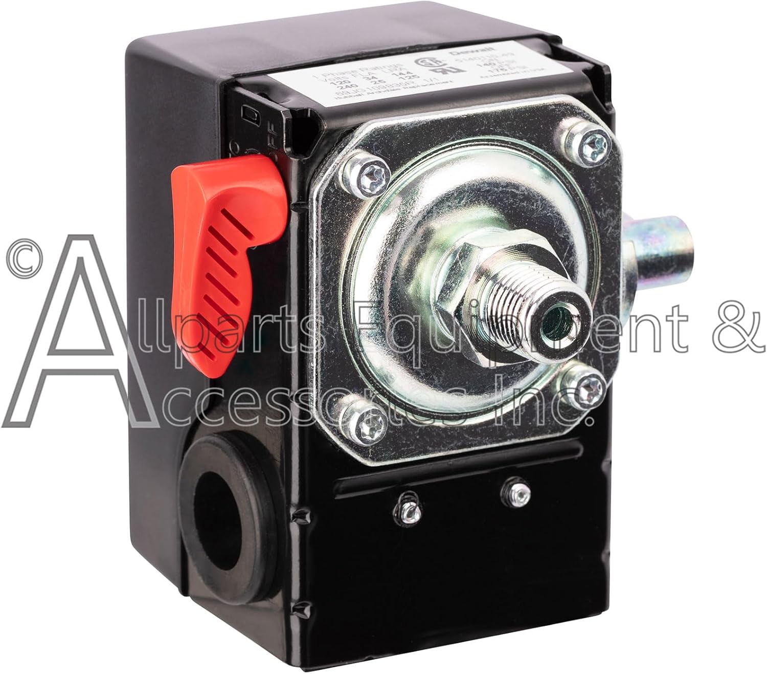
Figure 2: Bottom view illustrating the air connection port of the D20596 Pressure Switch.

Figure 3: Internal view of the D20596 Pressure Switch showing electrical terminals for Line (L1, L2) and Motor connections.
4. Operation
The D20596 Pressure Switch controls the air compressor's motor based on the air tank pressure. It features an ON-OFF operation mode and adjustable pressure settings.
- Initial Start-up: After installation, reconnect power to the compressor. The motor should start and build pressure until it reaches the factory-set "OFF" pressure (typically 175 PSI).
- Automatic Operation: As air is used and the tank pressure drops to the "ON" pressure (typically 140 PSI), the switch will automatically engage the compressor motor to refill the tank. When the "OFF" pressure is reached, the motor will shut off.
- Manual ON/OFF: The switch typically includes a manual lever (often red) to turn the compressor ON or OFF. Use this lever to manually stop the compressor when not in use or for maintenance.
- Adjustable Pressure Settings: The D20596 switch allows for adjustment of the cut-in (ON) and cut-out (OFF) pressure settings. These adjustments are usually made via internal screws. Refer to your compressor's manual or consult a qualified technician for safe adjustment procedures. Incorrect adjustment can lead to unsafe operating pressures.
5. Maintenance
Regular maintenance ensures the longevity and safe operation of your pressure switch and air compressor.
- Regular Inspection: Periodically inspect the pressure switch for any signs of damage, corrosion, or loose wiring connections.
- Check for Leaks: Listen for air leaks around the pressure switch connections. If leaks are detected, depressurize the system and re-seal the connections with appropriate thread sealant.
- Safety Valve Test: Regularly test the air compressor's safety relief valve according to the compressor manufacturer's instructions to ensure it functions correctly.
- Cleanliness: Keep the pressure switch free from dirt, dust, and moisture.
6. Troubleshooting
This section addresses common issues you might encounter with your D20596 Pressure Switch.
| Problem | Possible Cause | Solution |
|---|---|---|
| Compressor does not turn ON. |
|
|
| Compressor does not turn OFF (over-pressurizes). |
|
|
| Air leaks around switch. |
|
|
If troubleshooting steps do not resolve the issue, contact a qualified service technician.
7. Specifications
- Model: D20596
- Brand: DeVilbiss Craftsman
- Material: Metal
- Operation Mode: ON-OFF
- Product Dimensions: 5 x 3 x 2 inches
- Item Weight: 1.75 pounds
- Electrical Ratings (1 Phase):
- 120 Volts: 34 FLA (Full Load Amps), 144 LRA (Locked Rotor Amps)
- 240 Volts: 25 FLA (Full Load Amps), 125 LRA (Locked Rotor Amps)
- Pressure Settings:
- Cut-in (ON) Pressure: 140 PSI
- Cut-out (OFF) Pressure: 175 PSI
- Special Feature: Adjustable Pressure Settings
- Compatibility: Replacement for various Black and Decker, DeVilbiss, Porter Cable, and Sears Craftsman air compressors.
8. Warranty Information
The D20596 Pressure Switch comes with a 1-Year Manufacturer's Replacement Warranty. This warranty covers defects in materials and workmanship under normal use. For warranty claims or further details, please contact the manufacturer or your point of purchase.
9. Customer Support
For technical assistance, replacement parts, or any questions regarding the DeVilbiss Craftsman D20596 Pressure Switch, please refer to the contact information provided by your retailer or the manufacturer, Allparts Equipment. Always provide your product model number (D20596) when seeking support.
Manufacturer: Allparts Equipment