Introduction
The Proster VC837 is a true-RMS digital multimeter designed for accurate measurement of AC/DC voltage, AC/DC current, resistance, capacitance, frequency, temperature, duty cycle, diode, and continuity. It features a large backlit LCD display, non-contact voltage (NCV) detection, and a magnetic hanger strap for convenient use.
Safety Information
WARNING: To avoid electric shock or personal injury, read all safety information before using this product. Use the meter only as specified in this manual; otherwise, the protection provided by the meter may be impaired.
- This device is CE rated for safety, 600V CAT IV and 1000V CAT III.
- Always ensure the test leads are correctly connected and the function switch is set to the appropriate range before making any measurements.
- Do not apply more than the rated voltage, as marked on the meter, between terminals or between any terminal and earth ground.
- Inspect test leads for damaged insulation or exposed metal. Replace if damaged.
- Do not operate the meter if it appears damaged or if the case is open.
- Exercise extreme caution when working with voltages above 30V AC RMS, 42V peak, or 60V DC. These voltages pose a shock hazard.
- Always disconnect the circuit power and discharge all high-voltage capacitors before testing resistance, continuity, diodes, or capacitance.
- The meter features double fuse protection and overload protection on all ranges.
Package Contents
- Proster VC837 Digital Multimeter
- Test Leads (Red and Black)
- K-Type Thermocouple Temperature Probe
- Multimeter Magnetic Hanger Strap
- Portable Carrying Bag
- User Manual (this document)

Product Overview
Familiarize yourself with the components of your Proster VC837 Multimeter.

- LCD Display: Large backlit display for reading measurements.
- Function Buttons:
- SELECT/ID: Toggles between functions on a single rotary switch position (e.g., AC/DC voltage, diode/continuity).
- RANGE/REL: Manual range selection or relative measurement.
- HOLD/* : Data hold function or backlight activation.
- Rotary Switch: Selects the desired measurement function.
- Input Jacks:
- 10A: Input for high current measurements (up to 10A).
- COM: Common (negative) input for all measurements.
- VΩmA: Input for voltage, resistance, capacitance, frequency, temperature, diode, continuity, and low current measurements.
- Protective Case & Stand: Soft non-slip orange rubber sleeve for protection; built-in stand for hands-free viewing.
- Test Probes Slot: Convenient storage for test leads.
Setup
1. Battery Installation
The multimeter requires batteries for operation. To install or replace batteries:
- Ensure the multimeter is turned OFF.
- Locate the battery compartment cover on the back of the unit.
- Unscrew the retaining screw(s) and remove the cover.
- Insert new batteries, observing correct polarity (+ and -).
- Replace the cover and secure with the screw(s).
2. Connecting Test Leads
Always connect the black test lead to the COM jack. Connect the red test lead to the appropriate input jack based on the measurement type:
- For voltage, resistance, capacitance, frequency, temperature, diode, and continuity measurements, connect the red lead to the VΩmA jack.
- For current measurements up to 600mA, connect the red lead to the VΩmA jack.
- For high current measurements (up to 10A), connect the red lead to the 10A jack.
Operating Instructions
General Operation
- Turn the rotary switch to the desired measurement function.
- If the function has multiple modes (e.g., AC/DC voltage), press the SELECT/ID button to toggle between them.
- Connect the test leads to the circuit or component under test.
- Read the measurement on the LCD display.
- To turn off the multimeter, rotate the switch to the OFF position. The multimeter also features an Auto Power Off (APO) function to conserve battery life.
Specific Measurement Functions
1. Voltage Measurement (AC/DC)
- Set the rotary switch to V~ (AC Voltage) or V= (DC Voltage).
- Connect the red test lead to the VΩmA jack and the black lead to the COM jack.
- Connect the test leads in parallel across the component or circuit to be measured.
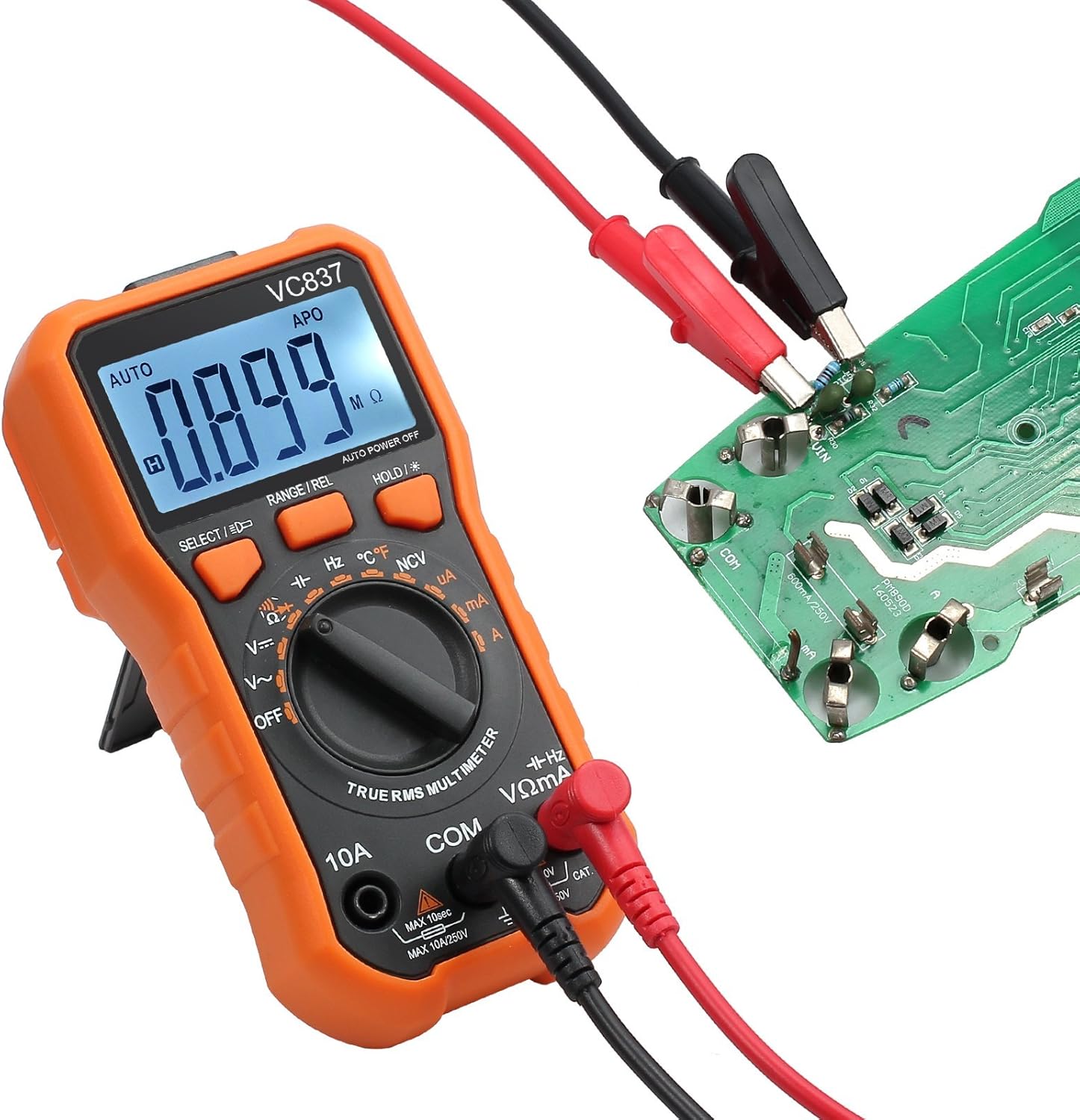
2. Resistance Measurement (Ω)
- Set the rotary switch to Ω.
- Connect the red test lead to the VΩmA jack and the black lead to the COM jack.
- Ensure the circuit is de-energized before measuring resistance. Connect the test leads across the component.
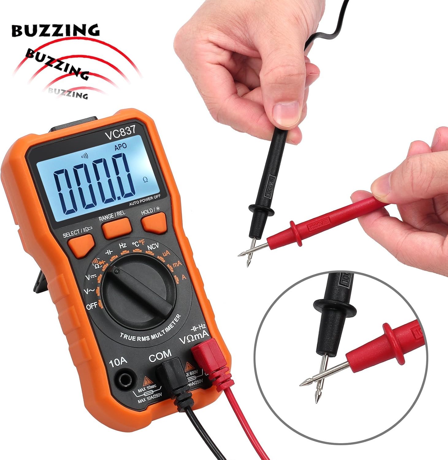
3. Continuity Test ())))
- Set the rotary switch to ))). Press SELECT/ID if necessary to select continuity mode.
- Connect the red test lead to the VΩmA jack and the black lead to the COM jack.
- Touch the test leads to the two points of the circuit to be tested. A continuous beep indicates a complete circuit (low resistance).

4. Temperature Measurement (°C/°F)
- Set the rotary switch to °C/°F.
- Connect the K-type thermocouple to the VΩmA and COM jacks, observing polarity.
- Place the thermocouple tip on or in the object whose temperature is to be measured.
- Press SELECT/ID to switch between Celsius and Fahrenheit.


5. Non-Contact Voltage (NCV) Detection
- Set the rotary switch to NCV.
- Move the top end of the multimeter near a live conductor. The meter will beep and the NCV indicator will light up if AC voltage is detected.
6. Other Functions (Current, Capacitance, Frequency, Diode, Duty Cycle)
Refer to the markings on the rotary switch and use the SELECT/ID button to access these functions. Always ensure correct lead connection and circuit conditions for accurate and safe measurements.
Using the Magnetic Hanger Strap
The included magnetic hanger strap allows for hands-free operation of your multimeter, attaching it to metal surfaces.
- Locate the loop attachment point on the back of your multimeter (if available) or use the existing stand slot.
- Attach the strap's loop to this point.
- The strong magnet on the strap can then be affixed to any ferrous metal surface, such as electrical panels or metal beams, holding the multimeter securely.

Maintenance
Cleaning
Wipe the case with a damp cloth and mild detergent. Do not use abrasives or solvents. Keep the input terminals free of dirt and moisture.
Battery Replacement
When the battery indicator appears on the LCD, replace the batteries immediately to ensure accurate readings. Follow the battery installation steps in the "Setup" section.
Fuse Replacement
If the current measurement function fails, the fuse may need replacement. Refer to the specifications for the correct fuse type and rating. Fuse replacement should only be performed by qualified personnel.
Troubleshooting
- No display or faint display: Check battery charge. Replace batteries if low.
- Incorrect readings:
- Ensure test leads are correctly connected to the appropriate input jacks.
- Verify the rotary switch is set to the correct function and range.
- Check for damaged test leads.
- Ensure the circuit is de-energized for resistance, continuity, and diode tests.
- Current measurement not working: Check the fuse.
- Multimeter turns off unexpectedly: Auto Power Off (APO) function is active. This is normal. If it turns off too quickly, check battery charge.
Specifications
| Feature | Detail |
|---|---|
| Display | 6000 Counts, Backlit LCD |
| Measurement Type | True-RMS |
| Safety Rating | CE Rated, 600V CAT IV, 1000V CAT III |
| Overload Protection | All ranges, Double Fuse |
| Functions | AC/DC Voltage, AC/DC Current, Resistance, Capacitance, Frequency, Temperature, Duty Cycle, Diode, Continuity, NCV |
| Special Features | Data Hold, Auto Power Off, Backlight, Built-in Stand, Test Probes Slot |
| Power Source | Battery Powered |
| Magnetic Hanger Strap | 14-inch, Universal loop attachment |
| Carrying Bag Size | 20*14*5cm (approx. 7.9 x 5.5 x 2 inches) |
Support and Warranty
For technical support or warranty inquiries, please contact Proster customer service through the retailer where the product was purchased or visit the official Proster website.
Please retain your proof of purchase for warranty claims.


