1. Product Overview
The Hormann EL 301 Light Barrier system is designed to enhance the safety of automated garage and entrance doors. This system functions by emitting a light beam; if this beam is interrupted, the door's movement is immediately halted, preventing potential accidents. It is particularly beneficial in environments with children or pets, providing an additional layer of protection.
The light barriers can be mounted directly onto the door frame or integrated into compatible STL columns, offering flexible installation options.
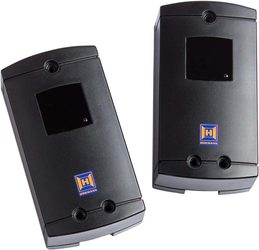
Image 1.1: Two Hormann EL 301 Light Barrier units. These black rectangular units feature a sensor window and the Hormann logo, designed for safety detection in automated door systems.
2. Safety Instructions
Please read and understand all safety instructions before installation and operation. Failure to follow these instructions may result in injury or damage to property.
- Installation should only be performed by qualified personnel in accordance with local electrical and safety regulations.
- Ensure the power supply to the door operator is disconnected before commencing any installation or maintenance work.
- Do not modify the light barrier units or their components.
- Keep the light barrier's optical surfaces clean and free from obstructions to ensure proper function.
- Regularly test the light barrier's functionality as described in the operating instructions.
3. Package Contents
The standard package for the Hormann EL 301 Light Barrier typically includes:
- Two (2) Hormann EL 301 Light Barrier units (transmitter and receiver).
- Connection cable: 2 x 10 meters, 2 wires.
- Mounting hardware (screws, anchors - may vary).
- Instruction Manual.
4. Specifications
| Feature | Detail |
|---|---|
| Control Voltage | 24 V DC |
| Connection Cable | 2 x 10 m, 2 wires |
| Protection Class | IP 65 |
| Dimensions (L x W x H) | 50 x 90 x 30 mm (each unit) |
| Weight | Approximately 640 grams (total package) |
| Manufacturer | Hormann |
| Model Number | EL 301 (Internal: 22ec65e8-195a-4c17-b49d-3b5028dd64d5) |
| UPC | 725084094003 |
5. Setup and Installation
Proper installation is crucial for the reliable operation of the light barrier. It is recommended that installation be carried out by a qualified technician.
- Preparation: Ensure the power supply to the door operator is completely disconnected. Identify suitable mounting locations on either side of the door opening, ensuring the units face each other directly and the beam path is clear.
- Mounting: Mount one light barrier unit (transmitter) on one side and the other (receiver) on the opposite side. They should be at the same height and aligned precisely to ensure the light beam can travel unobstructed between them. The units can be mounted directly to the door frame or integrated into compatible STL columns.
- Wiring: Connect the 2 x 10 m, 2-wire connection cable from each light barrier unit to the designated terminals on your door operator control unit. Refer to your door operator's manual for specific wiring diagrams. Ensure correct polarity for 24 V DC connections.
- Alignment: After mounting and wiring, restore power to the door operator. Most light barriers have an indicator light to confirm proper alignment. Adjust the position of the units slightly until the alignment indicator shows a stable signal.
- Testing: Perform a functional test. With the door in the open position, activate the closing cycle. While the door is closing, interrupt the light beam with an object (e.g., your hand or a box). The door should immediately stop and reverse or stop completely. Repeat this test multiple times to confirm consistent operation.
6. Operating Instructions
Once correctly installed and aligned, the Hormann EL 301 Light Barrier operates automatically as a safety device for your automated door system.
- The light barrier continuously monitors the area across the door opening.
- If an object or person breaks the light beam while the door is closing, the door's movement will be immediately interrupted. Depending on your door operator's settings, the door may stop and reverse to the open position or simply stop.
- The door will not resume closing until the obstruction is removed and the light beam is clear.
Important: The light barrier is a safety device but should not replace careful observation during door operation. Always ensure the path of the door is clear before activating it.
7. Maintenance
Regular maintenance ensures the longevity and reliable operation of your light barrier system.
- Cleaning: Periodically clean the optical lenses of both light barrier units with a soft, damp cloth. Dust, dirt, spiderwebs, or debris can obstruct the beam and cause false triggers or system malfunction. Do not use abrasive cleaners.
- Inspection: Visually inspect the units and wiring for any signs of damage, corrosion, or loose connections. Ensure the units remain securely mounted and properly aligned.
- Functional Test: Perform the functional test (as described in Section 5, point 5) at least once a month to confirm the light barrier is operating correctly.
8. Troubleshooting
If your Hormann EL 301 Light Barrier is not functioning as expected, consider the following common issues:
- Door does not close / Stops unexpectedly:
- Check for obstructions in the light beam path (e.g., leaves, debris, objects, spiderwebs).
- Clean the optical lenses of both units.
- Verify alignment of the transmitter and receiver units. Adjust if necessary until the alignment indicator (if present) shows a stable signal.
- Inspect wiring for loose connections or damage.
- No indicator light / No power:
- Ensure the door operator has power.
- Check wiring connections to the door operator control unit.
- Verify the control voltage (24 V DC) is present at the terminals.
- Door closes even with obstruction:
- This indicates a critical safety failure. Immediately disconnect power to the door operator.
- Re-check all wiring and alignment.
- If the issue persists, the light barrier units may be faulty and require replacement. Contact a qualified technician.
For issues not resolved by these steps, please contact Hormann customer support or a certified service technician.
9. Warranty and Support
Hormann products are manufactured to high-quality standards. For information regarding warranty coverage, terms, and conditions, please refer to the warranty documentation provided with your purchase or visit the official Hormann website.
For technical support, spare parts, or service inquiries, please contact your authorized Hormann dealer or Hormann customer service directly. When contacting support, please have your product model (EL 301) and any relevant purchase information available.


