1. Introduction
This manual provides comprehensive instructions for the installation and maintenance of the HD Switch Ignition Switch Wire Harness Repair Kit. This kit is designed to replace and repair the wire harness connection for specific ignition switches, ensuring proper electrical function.
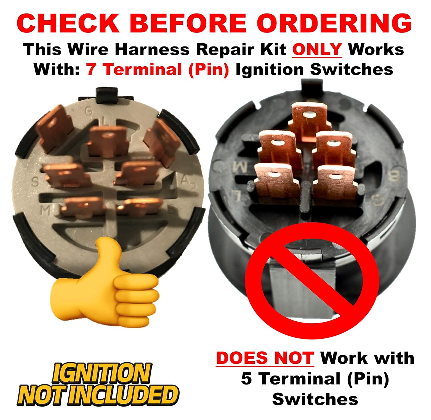
It is crucial to verify compatibility before proceeding with installation. This kit is specifically for 7-terminal, 4-position ignition switches.
2. Product Contents
The HD Switch Ignition Switch Wire Harness Repair Kit includes the following components:
- 7 Wires with Crimped Terminals: Pre-crimped wires for direct connection.
- 1 Connector: The main housing for the terminals.
- Butt Connectors: For splicing wires if necessary.
- Corrugate (Wire Loom): For protecting the assembled wire harness.


3. Compatibility
This repair kit is designed exclusively for specific ignition switch types. Please ensure your existing ignition switch matches the following criteria:
- 7 Terminal (Pin) Ignition Switches: The kit is compatible only with switches that have seven electrical terminals.
- 4 Position Ignition Switches: The kit is compatible only with switches that operate in four distinct positions (e.g., Off, Accessory, Run, Start).
Important: This kit is NOT compatible with 5-terminal, 3-position ignition switches.

4. Setup and Installation
Before beginning, ensure the vehicle's battery is disconnected to prevent electrical shorts or injury. Refer to your vehicle's service manual for specific instructions on accessing and removing the existing ignition switch harness.
- Identify Existing Wiring: Carefully note the color and position of each wire connected to your old ignition switch harness. It is highly recommended to take photographs or draw a diagram before disconnecting any wires.
- Remove Old Connector: Disconnect the old wire harness connector from the ignition switch. If the old wires are damaged, cut them as close to the old connector as possible.
- Prepare New Wires: The kit includes seven pre-crimped wires. Match the wire colors from your vehicle's existing wiring to the new wires provided in the kit. If the existing wires are too short or damaged, use the provided butt connectors to extend or repair them. Ensure all connections are secure and properly insulated.
- Insert Wires into New Connector: Carefully insert each crimped terminal of the new wires into the corresponding slot in the new connector housing. Ensure they click securely into place. Refer to your diagram or photographs to ensure correct terminal placement.
- Assemble Harness: Once all wires are securely in the connector, slide the corrugated wire loom over the assembled wires to protect them from abrasion and environmental damage.
- Connect to Ignition Switch: Plug the newly assembled wire harness connector firmly into the ignition switch.
- Reconnect Battery and Test: Reconnect the vehicle's battery. Test the ignition switch through all its positions (Off, Accessory, Run, Start) to ensure proper function of all associated electrical systems.


5. Operating
This product is a repair kit for an ignition switch harness. Its operation is passive, meaning it facilitates the proper function of the ignition switch rather than having an independent operational mode. Once correctly installed, the ignition switch and associated systems should operate as intended by the vehicle manufacturer.
Ensure the ignition switch functions smoothly through all its designated positions (Off, Accessory, Run, Start) and that all connected electrical components (e.g., lights, starter motor) respond correctly.
6. Maintenance
The HD Switch Ignition Switch Wire Harness Repair Kit requires minimal maintenance once installed. Periodically inspect the harness for any signs of wear, fraying, or damage to the corrugated loom. Ensure the connector remains firmly seated in the ignition switch.
If any damage is observed, disconnect the battery and inspect the affected area. Replace any damaged components as necessary to maintain electrical integrity and prevent future issues.
7. Troubleshooting
- No Power to Ignition Switch:
- Check battery connections and charge.
- Verify main fuses or circuit breakers.
- Ensure the harness connector is fully seated in the ignition switch.
- Engine Does Not Start (No Crank):
- Confirm the ignition switch is in the "Start" position.
- Check for proper connection of the starter wire within the harness.
- Inspect the starter motor and solenoid for faults.
- Intermittent Electrical Issues:
- Inspect all crimped terminal connections for looseness or corrosion.
- Ensure butt connectors (if used) are properly crimped and insulated.
- Check for damaged insulation on wires within the corrugated loom.
- Incorrect Terminal Placement:
- If functions are incorrect or non-responsive, disconnect the battery and re-verify that each wire terminal is inserted into the correct slot in the connector housing, matching your original wiring diagram.
8. Specifications
| Brand | HD Switch |
| Compatible Ignition Switches | 7 Terminal, 4 Position (e.g., John Deere GY20074, AM132807, AM133597) |
| Material | Plastic (Connector, Corrugate), Copper (Wires, Terminals) |
| Connector Type | Quick Connect |
| Package Dimensions | 5.67 x 5.63 x 1.34 inches |
| Item Weight | 5.93 ounces |
9. Warranty Information
Warranty information for this product was not available in the provided data. Please refer to the product packaging or contact HD Switch directly for details regarding warranty coverage.
10. Support
Support contact information for this product was not available in the provided data. For technical assistance or inquiries, please refer to the official HD Switch website or contact their customer service department.


