Introduction
This manual provides essential information for the proper setup, operation, and maintenance of your Treedix 6pcs 3.5mm Female Audio Jack Breakout Boards. These breakout boards are designed to simplify the integration of 3.5mm audio jacks into your electronic projects, offering easy access to all five pins of a TRRS connector.
Package Contents
Verify that all components are present in your package:
- 6 x Audio Jack Breakout Boards
- 6 x PJ307 Socket Audio Connectors (3.5mm Female)
- 6 x 5-pin Male Pin Headers
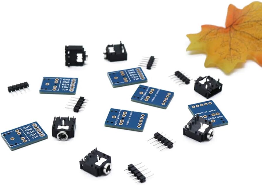
Image: Contents of the Treedix 6pcs 3.5mm Female Audio Jack Breakout Board package.
Product Overview
The Treedix 3.5mm Female Audio Jack Breakout Board provides a convenient way to interface 3.5mm audio jacks with breadboards or custom PCBs. These boards are designed for TRRS (Tip, Ring, Ring, Sleeve) connectors, which typically feature three conductors and a ground, unlike standard stereo connectors. This allows for additional functionalities such as microphone input or video signals, depending on the connected device.
The compact design makes these boards suitable for various applications, including media players, MP3/MP4 players, audio-video equipment, mobile phones, smartphones, PDAs, and car audio systems. Please note that these boards do not include a microphone jack directly on the breakout board itself, but rather provide access to the TRRS pins for external connection.
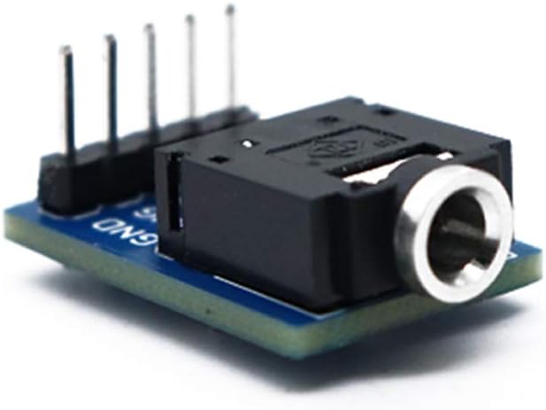
Image: Assembled 3.5mm Female Audio Jack Breakout Board.
Setup and Assembly
The Treedix 3.5mm Female Audio Jack Breakout Boards are shipped unassembled and require soldering. This allows for flexible integration into your projects. Basic soldering skills and equipment are necessary for assembly.
Required Tools:
- Soldering Iron
- Solder (e.g., lead-free or leaded electronic solder)
- Wire Strippers (if connecting wires directly)
- Safety Glasses
- Ventilation (e.g., fume extractor)
Assembly Steps:
- Prepare Components: Carefully unpackage the breakout boards, 3.5mm audio jack sockets, and 5-pin male headers.
- Position the Audio Jack: Align the 3.5mm female audio jack socket with the designated pads on the breakout board. Ensure the pins of the socket pass through the corresponding holes on the PCB.
- Solder the Audio Jack: Secure the audio jack in place (you may use a breadboard or helping hands). Carefully solder each pin of the audio jack to its respective pad on the breakout board. Ensure strong, clean solder joints without bridging connections.
- Position the Pin Header: Insert the 5-pin male header into the row of five holes on the breakout board. The pins are labeled GND, RNG, RSH, TSH, and TIP.
- Solder the Pin Header: Solder each pin of the male header to the breakout board. Again, ensure secure and clean solder joints.
- Inspect Solder Joints: After soldering, visually inspect all connections for cold joints, solder bridges, or insufficient solder. Re-solder any problematic connections.
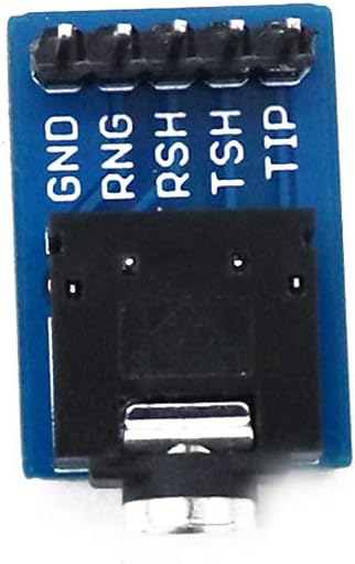
Image: Pinout labels on the Treedix 3.5mm Female Audio Jack Breakout Board.
Pinout Description:
- GND: Ground connection.
- RNG: Ring 1 (typically right audio channel or microphone).
- RSH: Ring 2 / Sleeve (typically left audio channel or video signal).
- TSH: Tip / Sleeve (typically left audio channel or video signal).
- TIP: Tip (typically left audio channel or microphone).
Note: The exact function of RNG, RSH, TSH, and TIP can vary depending on the TRRS standard (OMTP vs. CTIA) and the device connected. Refer to the documentation of your specific audio device for precise pin assignments.
Operating Instructions
Once assembled, the breakout board can be integrated into your electronic circuit. The 5-pin header allows for easy connection to breadboards, prototyping boards, or direct wiring to microcontrollers and other components.
- Connect to Circuit: Insert the assembled breakout board into a breadboard or connect its 5-pin header to your circuit using jumper wires. Ensure correct pin alignment (GND to ground, audio channels to appropriate inputs/outputs).
- Plug in Audio Device: Insert a 3.5mm audio plug (e.g., from headphones, speakers, or a microphone) into the female audio jack on the breakout board.
- Test Functionality: Apply power to your circuit and test the audio input/output as intended. For audio output, you should hear sound through connected speakers or headphones. For audio input (e.g., microphone), verify signal reception through your circuit.
These boards are ideal for prototyping and custom audio projects, allowing you to experiment with different audio configurations.
Maintenance
The Treedix 3.5mm Female Audio Jack Breakout Boards require minimal maintenance. Follow these guidelines to ensure longevity:
- Keep Clean: Periodically clean the boards with a soft, dry brush to remove dust or debris. Avoid using liquids directly on the electronic components.
- Store Properly: When not in use, store the boards in an anti-static bag or a dry, cool environment to prevent damage from static discharge or moisture.
- Handle with Care: Avoid excessive force when inserting or removing 3.5mm plugs to prevent damage to the jack or solder joints.
- Inspect Connections: Regularly check solder joints for any signs of cracking or corrosion, especially if the board is subjected to vibration or frequent handling.
Troubleshooting
If you encounter issues with your Treedix 3.5mm Female Audio Jack Breakout Board, consider the following troubleshooting steps:
- No Audio/Signal:
- Verify all solder joints are solid and free of bridges.
- Check that the 3.5mm plug is fully inserted into the jack.
- Confirm correct pin connections (GND, TIP, RNG, RSH, TSH) to your circuit.
- Test the audio source/device with another known working jack/cable.
- Intermittent Connection:
- Inspect the 3.5mm plug for damage or debris.
- Check for loose solder joints on the breakout board.
- Ensure the breakout board is securely seated in the breadboard or connections are firm.
- Incorrect Channel Output or Functionality:
- Review the pinout diagram and your circuit connections. TRRS standards (OMTP vs. CTIA) can differ in pin assignments for microphone/ground.
- If using a TRRS plug, ensure your circuit is designed to handle all four conductors. Some TRRS plugs may short certain pins if inserted into a jack not designed for that specific configuration, potentially causing issues like the "Ring and sleeve connected together" scenario mentioned in user feedback.
Specifications
| Material | Plastic + Metal |
| Dimensions (L x W x H) | 21.5mm x 15.5mm x 8mm (approx.) |
| Connector Type | 3.5mm Female Audio Jack (TRRS compatible) |
| Number of Pins | 5 (GND, RNG, RSH, TSH, TIP) |
| Color | Black (connector), Blue (PCB) |
| Item Weight | 0.81 ounces (for the set of 6) |
| Model Number | PJ-3076 |
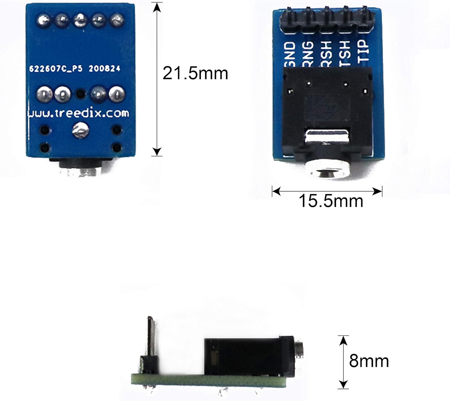
Image: Dimensional drawing of the Treedix 3.5mm Female Audio Jack Breakout Board.

Image: PCB layout and dimensions in inches.
Warranty and Support
For any questions, technical assistance, or support regarding your Treedix 3.5mm Female Audio Jack Breakout Boards, please contact Treedix customer service. Refer to your purchase documentation for specific warranty details and contact information.
You can also visit the official Treedix store on Amazon for more information and support resources: Treedix Store


