
Introduction
The Youmile DC 6-30V Programmable Timer Delay Relay Module is a versatile control unit designed for precise timing applications. It operates within a wide voltage range of DC 6V to 30V and can also be powered via a Micro USB 5V input. Featuring a clear LED display, this module allows users to configure various timing parameters such as conduction time (OP), stop time (CL), and loop operation times (LOP). All settings are saved permanently, ensuring consistent performance. This module is suitable for a wide array of applications including smart home automation, industrial control systems, automatic irrigation, and protective equipment.

Figure 1: Youmile Timer Delay Relay Module. This image shows the top view of the module, highlighting the digital LED display, the four control buttons (SET, STOP, UP, DOWN), and the relay component.
1. Setup and Wiring
Before connecting the module, ensure your power source and load meet the specified requirements. The module supports a DC input voltage range of 6V to 30V. Alternatively, it can be powered via a 5V Micro USB connection.
- Power Supply: Connect DC 6V-30V to the input terminals or use a Micro USB 5V power supply.
- Trigger Signal: The high-level trigger input accepts 3V-24V. The module includes a built-in diode for reverse polarity protection.
- Load Connection: The relay's normally open (NO) contact can handle a maximum load of AC 250V/10A or DC 30V/10A.

Figure 2: Wiring Diagram - Weak Current Controlling Strong Current. This diagram illustrates how to connect the module when a low-power trigger signal controls a higher-power load. The DC 6-30V input powers the module, and the trigger signal (3V-24V) activates the relay. The load is connected to the NO (Normally Open) and COM (Common) terminals of the relay, with the AC or DC power source for the load connected separately.
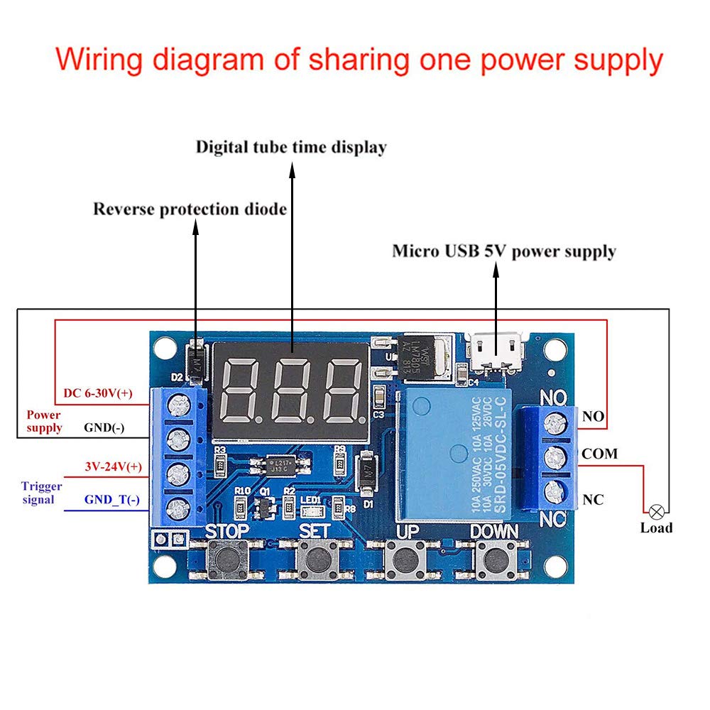
Figure 3: Wiring Diagram - Sharing One Power Supply. This diagram shows a configuration where the module and the load share a common power supply (DC 6-30V). The trigger signal (3V-24V) activates the relay, and the load is connected to the NO and COM terminals, drawing power from the same source as the module.
2. Operating Instructions
The module features a digital tube time display and four control buttons: SET, STOP, UP, and DOWN.
2.1. Display and Auto-Off Feature
The digital display shows current settings or countdowns. If no operation is performed within 5 minutes, the digital display will automatically turn off to save power. Press any button to reactivate the display.
2.2. Parameter Setting Modes
The module supports various operating modes, each defined by specific parameters: OP (conduction time), CL (stop time), and LOP (loop times). These parameters can be set individually and are permanently stored even after power loss.
- Entering Setting Mode: Press and hold the SET button for a few seconds until the display shows "P-X" (where X is the mode number).
- Selecting a Mode: Use the UP and DOWN buttons to cycle through the available operating modes (e.g., P-1.1, P-1.2, P-2, P-3.1, P-3.2, P-4). Refer to the detailed mode descriptions for specific functionalities.
- Setting Parameters (OP, CL, LOP): Once a mode is selected, briefly press SET. The display will flash the first parameter (e.g., OP). Use UP and DOWN to adjust the value. Briefly press SET again to move to the next parameter (e.g., CL, then LOP).
- Adjusting Time Units: While a parameter (OP, CL) is flashing, press the STOP button to switch between time units: "xxx." (seconds, 0.1s to 999s), "xx.x" (minutes, 0.1min to 99.9min), or "x.x.x" (hours, 0.1h to 99.9h).
- Saving Settings: After setting all parameters for the chosen mode, press and hold the SET button until the display stops flashing and returns to the main display. This saves all parameters permanently.
2.3. STOP Button Functionality
In the main display interface, a short press of the STOP button can toggle the relay's enable/disable state. The display will show "ON" or "OFF" to indicate the current state. When "OFF", the relay will not conduct, even if triggered.
2.4. Common Applications
This module is widely used for:
- Smart home automation
- Industrial control systems
- Automatic irrigation systems
- Ventilation control
- Protective equipment timing
3. Maintenance
The Youmile Timer Delay Relay Module is designed for durability and requires minimal maintenance. To ensure optimal performance and longevity:
- Keep Clean: Regularly clean the module with a soft, dry cloth to prevent dust accumulation, especially around the buttons and display.
- Avoid Moisture: Protect the module from water, high humidity, and corrosive environments.
- Temperature Range: Operate the module within its specified temperature range of -20°C to 60°C.
- Secure Connections: Periodically check all wiring connections to ensure they are secure and free from corrosion.
- Power Supply: Always use a stable power supply within the specified voltage range (DC 6-30V or Micro USB 5V).
4. Troubleshooting
If you encounter issues with your Youmile Timer Delay Relay Module, consider the following common troubleshooting steps:
- Module Not Powering On:
- Verify the power supply voltage is within DC 6-30V or 5V via Micro USB.
- Check power connections for proper polarity and secure contact.
- Ensure the Micro USB cable is functional if using that power source.
- Relay Not Activating:
- Check if the trigger signal voltage is within 3V-24V and connected correctly.
- Ensure the module is not in "OFF" state (check with a short press of the STOP button).
- Verify the timing parameters (OP, CL, LOP) are set correctly for the desired operation mode.
- Confirm the load is connected to the correct relay terminals (NO/COM) and is within the maximum load specifications.
- Display Not Showing:
- The display automatically turns off after 5 minutes of inactivity. Press any button to reactivate it.
- If still off, check power supply as above.
- Parameters Not Saving:
- Ensure you press and hold the SET button after configuring parameters until the display stops flashing to save them.
5. Specifications
| Feature | Value |
|---|---|
| Model Number | DR-YM-335 |
| Operating Voltage | DC 6V - 30V (supports Micro USB 5V power supply) |
| Operating Current | 50mA |
| Static Current | 20mA |
| Trigger Signal | High-level trigger (3V - 24V) |
| Maximum Load (NO) | < AC 250V/10A, < DC 30V/10A |
| Timing Range | 0.1 seconds to 999 minutes (continuously adjustable) |
| Working Temperature | -20°C to 60°C |
| Dimensions | 6.4 x 3.8 x 1.7 cm (L x W x H) |
| Power Consumption | 300 Watts (maximum switched load) |
| UPC / GTIN | 882122199998 |

Figure 4: Module Bottom View. This image displays the underside of the module, showing the circuit board layout and various pin labels for connections.
6. Warranty and Support
For detailed support, additional resources, or warranty information, please refer to the official Youmile product documentation. A user manual is often available online. For this product, a user manual can be found at: https://bit.ly/2YrfL8a.
For further assistance, please contact Youmile customer support through their official channels.
