1. Safety Information
Please read and understand all safety warnings and operating instructions before using this instrument. Failure to follow these instructions may result in electric shock, fire, or serious injury.
- Always ensure the multimeter is in good working condition before use. Inspect for any damage to the casing or test leads.
- Do not apply voltage exceeding the maximum rated input (400V DC or AC effective value).
- Use caution when working with voltages above 30V AC RMS, 42V peak, or 60V DC. These voltages pose a shock hazard.
- Ensure the test leads are properly connected to the correct input terminals for the measurement being performed.
- Do not use the multimeter if the battery cover is not securely closed.
- Replace batteries immediately when the low battery indicator appears to ensure accurate readings.
- Avoid using the device in wet environments or during electrical storms.
- Always disconnect power to the circuit before making resistance or continuity measurements.
2. Product Overview and Package Contents
The Walfront Digital Multimeter is a compact, auto-ranging device designed for measuring AC/DC voltage, resistance, frequency, continuity, and non-contact voltage detection. It features an LCD display and an integrated flashlight for convenience.
2.1 Package Contents
- Walfront Digital Multimeter (ADMS1CL or ADMS1)
- Test Leads (Red and Black)
- Lanyard
- User Manual
2.2 Multimeter Components

Image 2.1: Labeled diagram of the Walfront Digital Multimeter, showing the non-contact sensor probe, LCD screen, power switch, mode/flashlight switch, voltage signal indicator, and input terminals.
- Non-contact sensor probe: Used for Non-Contact Voltage (NCV) detection.
- LCD screen: Displays measurement readings, units, and indicators.
- Power switch: Turns the device on or off.
- Switch mode/Flashlight switch: Toggles between measurement modes and activates the LED flashlight.
- Voltage signal indicator: LED bar graph indicating detected voltage strength.
- Input Terminal (COM): Common negative input for test leads.
- Input Terminal (INPUT): Positive input for test leads.
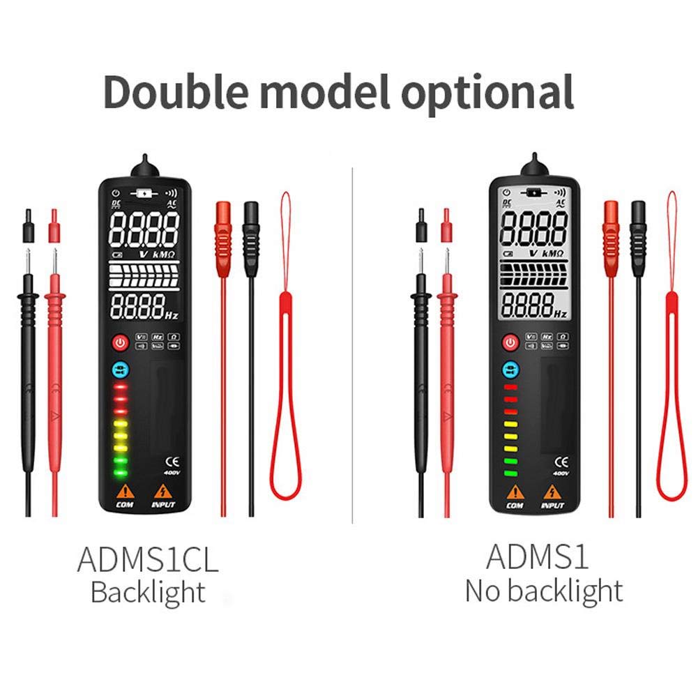
Image 2.2: Comparison showing the ADMS1CL model with a backlit display and the ADMS1 model without a backlight.
3. Setup
3.1 Battery Installation
The multimeter requires one 3V AAA battery (not included) for operation.
- Locate the battery compartment on the back of the multimeter.
- Use a screwdriver to open the battery compartment cover.
- Insert one 3V AAA battery, observing the correct polarity (+/-) as indicated inside the compartment.
- Securely close the battery compartment cover.
4. Operating Instructions
4.1 Power On/Off
- To power on the multimeter, press the Power Switch button.
- To power off, press and hold the Power Switch button until the display turns off.
- The device features an automatic shutdown function after approximately 2 minutes of inactivity to conserve battery life.
4.2 Automatic Measurement Mode
Upon powering on, the multimeter defaults to an intelligent automatic measurement mode. In this mode, the device automatically identifies and measures AC/DC voltage, resistance, and continuity without manual range selection.

Image 4.1: The multimeter being used to test electrical components on a circuit board, demonstrating its application in general electrical testing.
4.3 Manual Mode Selection
Press the Mode/Flashlight Switch button to cycle through specific measurement functions:

Image 4.2: Icons illustrating the multimeter's capabilities: AC Voltage, DC Voltage, Resistance, Frequency, Continuity, Flashlight, V-Alert, and Live Wire detection.
- Voltage AC (V~): For measuring alternating current voltage. Connect test leads to the circuit in parallel.
- Voltage DC (V-): For measuring direct current voltage. Connect test leads to the circuit in parallel, observing polarity.
- Resistance (Ω): For measuring electrical resistance. Ensure the circuit is de-energized before connecting test leads across the component.
- Frequency (Hz): For measuring the frequency of an AC signal.
- Continuity (•))): For checking if a circuit is complete. The multimeter will beep if continuity is detected. Ensure the circuit is de-energized.
4.4 Non-Contact Voltage (NCV) Detection
The multimeter can detect AC voltage without direct contact, enhancing safety.
- Ensure the multimeter is powered on.
- Place the non-contact sensor probe near the conductor or outlet.
- The voltage signal indicator LEDs will illuminate, and an audible beep will sound, with intensity increasing as the voltage strength increases.
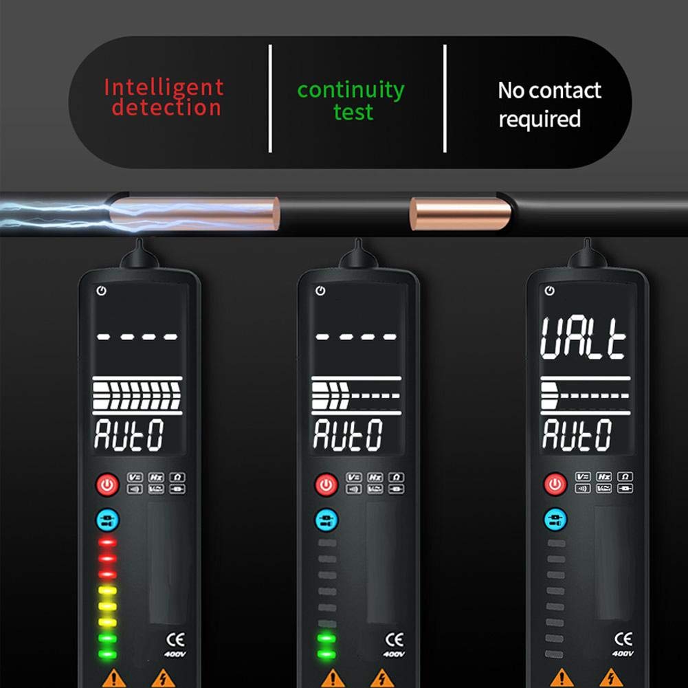
Image 4.3: Demonstrates intelligent detection, continuity testing, and non-contact voltage detection capabilities of the multimeter.
4.5 Live Wire Detection
This function helps identify live wires in an AC circuit.
- Ensure the multimeter is powered on.
- Place the non-contact sensor probe near the wire or into the slot of an outlet.
- The multimeter will indicate a live wire with a stronger signal (more LEDs illuminated) compared to a neutral wire.

Image 4.4: Illustrates the difference in readings and LED indications when performing a Neutral Check versus a Live Check with the multimeter.
4.6 LED Flashlight Operation
The integrated LED flashlight assists in working in dimly lit areas.
- To turn on the flashlight, press and hold the Mode/Flashlight Switch button.
- To turn off the flashlight, press and hold the Mode/Flashlight Switch button again.

Image 4.5: The multimeter's LED flashlight in operation, illuminating a work area for convenient testing in low-light conditions.
5. Maintenance
5.1 Cleaning
To clean the multimeter, wipe the casing with a damp cloth and a mild detergent. Do not use abrasive cleaners or solvents. Ensure the device is powered off and disconnected from any circuits before cleaning.
5.2 Battery Replacement
When the low battery indicator appears on the LCD, replace the battery promptly to ensure accurate measurements. Refer to Section 3.1 for battery installation instructions.
5.3 Storage
If the multimeter will not be used for an extended period, remove the battery to prevent leakage and damage to the device. Store the multimeter in a cool, dry place, away from direct sunlight and extreme temperatures.
6. Troubleshooting
- No display or weak display: Check battery installation. Replace with a fresh 3V AAA battery if necessary.
- Inaccurate readings: Ensure test leads are properly connected. Verify the correct measurement mode is selected (if not using auto mode). Replace battery if low battery indicator is present.
- No continuity beep: Ensure the circuit is de-energized. Check if the component being tested is actually continuous.
- NCV not detecting voltage: Ensure the probe is close enough to the conductor. Verify the voltage is within the detectable range.
7. Specifications
- Item Type: Smart Multimeter
- Material: ABS
- Color: Black
- Size: Approx. 150x40x17mm / 5.9x1.6x0.7in
- Weight: Approx. 120g / 4.2oz
- Display: LCD, 2000 digits maximum display value
- Sampling Rate: Approximately 3 times / second
- Auto Range: Yes
- Full Range Overload Protection: Yes
- Maximum Voltage Allowed at Measuring Terminal: DC: 400V or AC: 400V (effective value)
- Working Height: 2000m
- Automatic Shutdown Time: Approximately 2 minutes
- Working Power Supply: 1x 3V AAA battery (not included)
- DC Voltage Range: 400V
- DC Voltage Resolution: 0.01V
- DC Voltage Accuracy: ± 0.8% reading + 3 words
- Sensitivity: Minimum 0.5V DC voltage
- Maximum Input Voltage: 400V DC or AC effective value
8. Warranty and Support
For warranty information or technical support, please refer to the product packaging or contact Walfront customer service directly through their official channels. Keep your purchase receipt for warranty claims.
