
1. Introduction
The Lenel LNL-500 Intelligent System Controller (ISC) is designed as the core access control engine for an OnGuard system. It delivers robust power, performance, and flexibility for demanding security applications. The ISC facilitates the connection of various Input Control Modules, Output Control Modules, and Card Reader Interface Modules, forming a comprehensive access control solution.
Key features include communication via RS-232/RS-485, modem dial-up, or Ethernet TCP/IP, storage for up to 12,500 cardholders, and support for multiple card formats. This manual provides essential information for the proper installation, operation, and maintenance of your LNL-500 ISC.
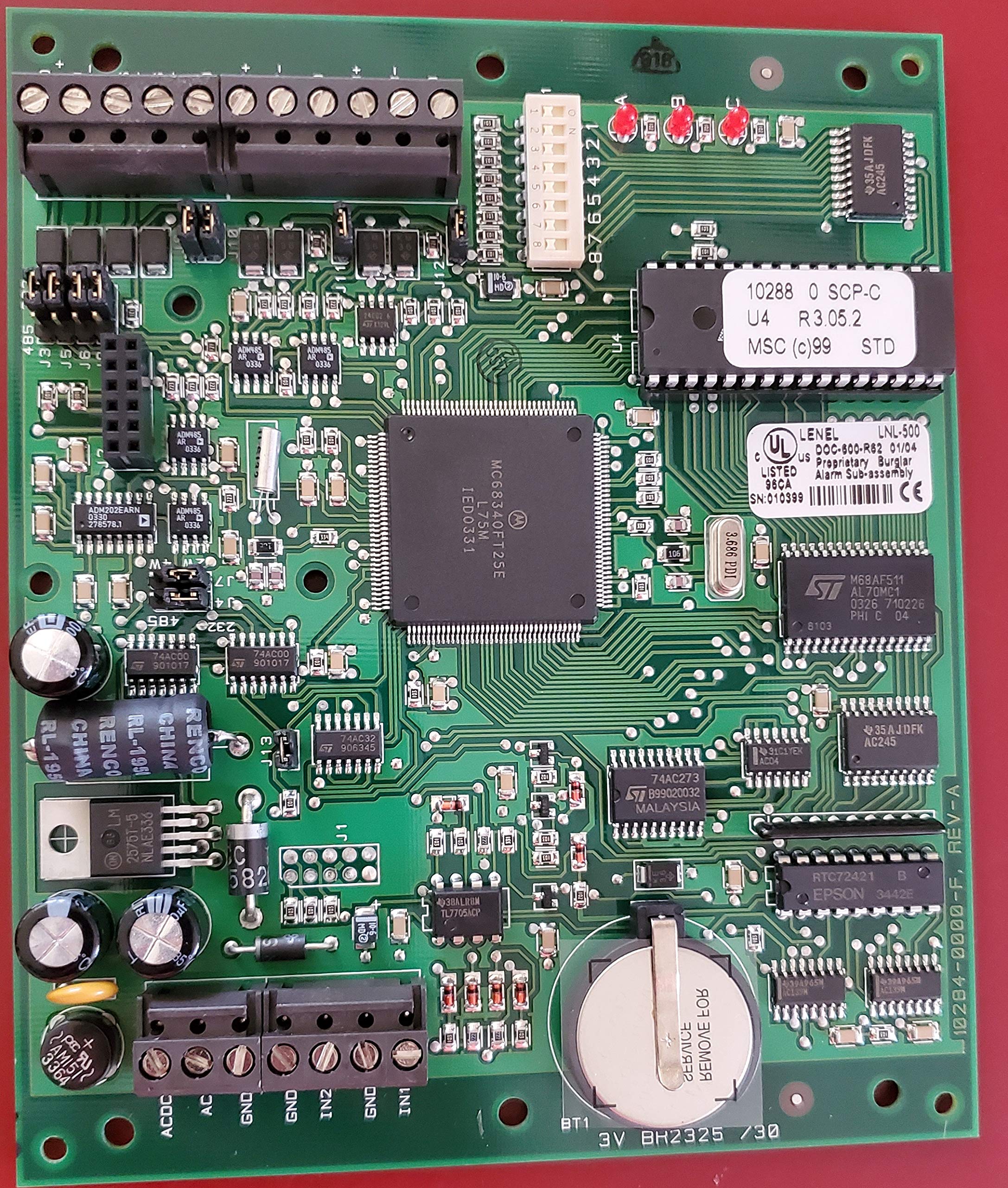
Figure 1: Lenel LNL-500 Intelligent System Controller (ISC) main unit. This image shows the green circuit board of the LNL-500, highlighting its various connectors and components.
2. Safety Information
Read all instructions carefully before installing or operating the LNL-500 ISC. Failure to follow these instructions may result in damage to the device, property, or personal injury.
- Qualified Personnel: Installation and servicing should only be performed by qualified personnel.
- Power Disconnection: Always disconnect power before performing any installation, maintenance, or troubleshooting procedures.
- Proper Voltage: Ensure the power supply matches the specified voltage requirements (12 VAC or 12 VDC). Incorrect voltage can damage the unit.
- Environmental Conditions: Install the device in a dry, well-ventilated area, away from extreme temperatures, humidity, and direct sunlight.
- ESD Precautions: Take electrostatic discharge (ESD) precautions when handling the circuit board to prevent damage to sensitive components.
3. Setup and Installation
3.1. Mounting
The LNL-500 ISC is typically mounted within an enclosure. Secure the unit using appropriate fasteners to a stable surface, ensuring adequate space for cable routing and ventilation.
3.2. Power Connection
Connect a 12 VAC or 12 VDC power source to the designated power input terminals on the LNL-500. Verify the polarity for DC connections. Ensure the power supply is capable of providing sufficient current for the ISC and all connected downstream devices.
3.3. Communication Setup
The ISC supports various communication methods for host connectivity:
- RS-232/RS-485: For direct wire connections, configure the appropriate jumpers or switches for RS-232 or RS-485 multidropped communication. The baud rate is 38.4 Kbps.
- Ethernet TCP/IP: Connect a standard Ethernet cable to the RJ45 port. Configure network settings (IP address, subnet mask, gateway) as required by your network infrastructure.
- Modem Dial-up: For remote communication, connect a compatible modem to the designated port and configure dial-up parameters.
3.4. Downstream Device Connections
The LNL-500 ISC provides two downstream 2-wire RS-485 channels or one 4-wire RS-485 channel. These channels are used to connect various modules and readers:
- Input Control Modules (e.g., LNL-1100): Connect these modules to expand input capabilities.
- Output Control Modules (e.g., LNL-1200): Connect these modules to expand output capabilities.
- Card Reader Interface Modules (e.g., LNL-1300, LNL-1320): Connect these modules to interface with card readers.
Up to 32 readers or 16 devices (LNL-1100, LNL-1200, LNL-1300, LNL-1320) can be connected per ISC. Each device utilizes one unique device address on the RS-485 bus. Refer to the specific module's documentation for detailed wiring and addressing instructions.
4. Operation
Once properly installed and configured, the LNL-500 ISC operates as the central processing unit for your access control system. It manages cardholder data, processes access requests, and controls connected input/output modules and readers.
- Cardholder Management: The ISC can store up to 12,500 cardholders. Cardholder data, access levels, and schedules are typically managed through the OnGuard software platform.
- Card Format Support: The system supports up to 8 different card formats simultaneously, allowing for integration with various credential types.
- Anti-Passback: Enhanced anti-passback capabilities prevent unauthorized re-entry or tailgating by enforcing entry/exit rules.
- Real-time Updates: Flash memory allows for real-time program updates, ensuring the system can be easily upgraded with new features or security patches.
- LED Indicators: The LNL-500 features LED indicators to display operational status, communication activity, and fault conditions. Refer to the technical documentation for a detailed explanation of LED patterns.
5. Maintenance
Regular maintenance helps ensure the longevity and reliable operation of your LNL-500 ISC.
- Cleaning: Periodically clean the exterior of the unit with a soft, dry cloth. Do not use liquid cleaners or solvents. Ensure the unit is powered off before cleaning.
- Firmware Updates: Check the manufacturer's website for available firmware updates. Apply updates as recommended to benefit from performance improvements and security enhancements. Follow all instructions provided with the update package.
- Cable Inspection: Periodically inspect all connected cables for signs of wear, damage, or loose connections.
- Environmental Check: Ensure the operating environment remains within specified temperature and humidity ranges.
6. Troubleshooting
This section provides solutions to common issues you might encounter with the LNL-500 ISC.
6.1. No Power / Unit Not Responding
- Check Power Supply: Verify that the 12 VAC or 12 VDC power supply is connected correctly and providing the specified voltage.
- Inspect Fuses: Check for any blown fuses on the power input.
- Power Cycle: Disconnect and reconnect power to the unit.
6.2. Communication Issues
- Network Connectivity (Ethernet): Ensure the Ethernet cable is securely connected and network settings (IP address, subnet mask) are correct. Verify network activity LEDs.
- RS-232/RS-485: Check cable continuity, proper wiring (polarity for RS-485), and termination resistors if applicable. Verify baud rate settings.
- Host Software: Ensure the OnGuard host software is running and configured to communicate with the ISC.
6.3. Downstream Device Issues
- Device Addressing: Confirm that each connected downstream device (LNL-1100, LNL-1200, LNL-1300, LNL-1320) has a unique address.
- Wiring: Check the RS-485 wiring between the ISC and the downstream devices for proper connections and polarity.
- Power to Devices: Ensure downstream devices are receiving adequate power.
If issues persist, consult the detailed technical documentation or contact Lenel technical support.
7. Specifications
| Feature | Detail |
|---|---|
| Model Number | LNL-500 |
| Input Power | 12 VAC or 12 VDC |
| Host Communications | 38.4 Kbps direct wire (RS-232/RS-485 multidropped), Ethernet TCP/IP, or dial-up |
| Cardholder Capacity | Up to 12,500 |
| Card Format Support | Up to 8 different formats simultaneously |
| Downstream Channels | Two 2-wire RS-485 or one 4-wire RS-485 |
| Max Downstream Devices | 32 readers or 16 devices (LNL-1100, LNL-1200, LNL-1300, LNL-1320) |
| Memory | Flash memory for real-time program updates |
| Anti-Passback | Enhanced capabilities |
| Display Type | LED indicators |
| Material | Plastic |
| Dimensions (L x W x H) | 18.29 x 13.46 x 7.62 cm (approx.) |
| Weight | 249 g (approx.) |
| UPC | 643690809845 |
8. Warranty and Support
For detailed warranty information, please refer to the official Lenel product warranty statement available on their website or included with your purchase documentation. Lenel provides technical support for its products.
If you require assistance with installation, configuration, or troubleshooting beyond the scope of this manual, please contact Lenel technical support through their official channels. Have your product model number (LNL-500) and any relevant system information ready when contacting support.
Lenel Website: www.lenel.com