Introduction
This manual provides essential information for the safe and effective installation, operation, and maintenance of the Fafeicy LT1-20 2P Low Voltage Arrester Module. Please read these instructions carefully before installation and use to ensure proper function and safety.
Safety Information
WARNING: Electrical installation should only be performed by qualified personnel. Failure to follow these instructions may result in electric shock, fire, or serious injury.
- Always disconnect power before installing or servicing the device.
- Ensure all wiring complies with local and national electrical codes.
- Do not operate the device if it appears damaged.
- This device is designed for specific voltage and current ratings. Do not exceed these limits.
Product Overview
The Fafeicy LT1-20 is a 2-pole low voltage surge protective device (SPD) designed for electrical engineering power protection. It features a plug-in module design for easy maintenance and rail installation for convenient setup. The device incorporates precise internal components for strong conductivity and effective surge protection.
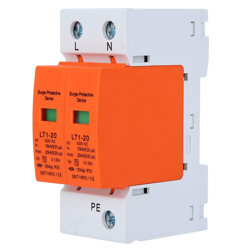
Figure 1: Front and side view of the Fafeicy LT1-20 Low Voltage Arrester Module. The device is white with an orange protective module, showing connection terminals and product specifications.

Figure 2: Close-up view of the surge protective device, highlighting the LT1-20 model and key specifications printed on the orange module, including Uc, In, Imax, and Up values.
Specifications
| Parameter | Value |
|---|---|
| Item Type | Device |
| Rated Current (In) | 10kA |
| Setting Current (Imax) | 20kA |
| Installation Method | Rail installation |
| Arc Extinguishing Medium | Magnetic blowing |
| Rated Voltage (Uc) | 420V AC |
| Number of Main Contacts | 2P |
| Scope of Application | Electrical Engineering |
| Wiring Method | 3-phase 4-wire |
| Type | Level 2 |
| Response Time | 0.2 seconds |
| Item Weight | 7.1 ounces |
Setup and Installation
The LT1-20 surge protective device is designed for rail installation within an electrical panel. Ensure all power is disconnected before proceeding.
Installation Steps:
- Power Disconnection: Turn off the main power supply to the electrical panel where the device will be installed. Verify power is off using a voltage tester.
- Mounting: Securely attach the LT1-20 module onto a standard DIN rail within the electrical panel. The device features a clip mechanism for easy rail mounting.
- Wiring: Connect the device according to the 3-phase 4-wire wiring method. The terminals are clearly marked L (Line), N (Neutral), and PE (Protective Earth).
- Connect the Line (L) conductor to the 'L' terminal.
- Connect the Neutral (N) conductor to the 'N' terminal.
- Connect the Protective Earth (PE) conductor to the 'PE' terminal.
- Verification: Double-check all connections to ensure they are tight and correctly wired.
- Power Restoration: Once installation is complete and verified, restore power to the electrical panel.

Figure 3: Top view of the Fafeicy LT1-20 module, clearly showing the 'L' (Line), 'N' (Neutral), and 'PE' (Protective Earth) terminals for electrical wiring connections.

Figure 4: Side view of the Fafeicy LT1-20, illustrating the design for rail installation. The yellow clip at the bottom facilitates secure attachment to a DIN rail.
Operating Instructions
The Fafeicy LT1-20 is an automatic surge protective device that operates passively. Once installed and powered, it continuously monitors the electrical system for voltage surges and diverts excess energy to ground, protecting connected equipment.
Status Indicator:
The device features a visual status indicator on each protective module (the orange part).
- Green Indicator: Indicates normal operation. The surge protection function is active.
- Red Indicator: Indicates that the protective module has been activated due to a surge and needs replacement.

Figure 5: Front view of the Fafeicy LT1-20 showing both protective modules with green status indicators, signifying normal operational status.
Maintenance
The Fafeicy LT1-20 is designed for low maintenance. Regular visual inspection is recommended.
- Visual Inspection: Periodically check the status indicators on the protective modules. If an indicator is red, the module has absorbed a surge and requires replacement.
- Module Replacement: The plug-in module design allows for easy replacement of individual protective modules without disconnecting the entire device from the rail.
- Disconnect power to the circuit containing the SPD.
- Carefully pull out the faulty module from its base.
- Insert a new, identical replacement module firmly into the base.
- Restore power and verify the new module's indicator is green.
- Cleaning: If necessary, gently wipe the exterior of the device with a dry, soft cloth. Do not use liquid cleaners or solvents.
Troubleshooting
| Problem | Possible Cause | Solution |
|---|---|---|
| Status indicator is red. | The protective module has absorbed a voltage surge and is no longer functional. | Replace the faulty protective module as described in the Maintenance section. |
| Device does not appear to be functioning (e.g., no indicator light, or system still experiences surges). | Incorrect wiring, no power to the circuit, or device damage. |
|
Disposal
When the device reaches the end of its service life, dispose of it according to local regulations for electronic waste. Do not dispose of electrical equipment in general household waste.