1. Introduction
Thank you for choosing the QWORK Air Compressor Pressure Switch, Model WD3785. This device is designed to automatically regulate the pressure in your air compressor system, ensuring efficient and safe operation. This manual provides essential information for proper installation, operation, and maintenance of your pressure switch.
2. Safety Information
Please read all safety instructions carefully before installation and operation to prevent injury or damage to the equipment.
- Power Disconnection: Always ensure the power supply to the air compressor is completely disconnected before attempting any installation, maintenance, or adjustment.
- Thread Compatibility: This unit is built with G1/4 BSP joints. It is not compatible with NPT-threaded (U.S.) air systems. Attempting to force incompatible threads can cause leaks and damage.
- Sealing Joints: Use appropriate PTFE (Teflon) tape or thread sealant on all threaded connections to ensure an airtight seal and prevent leaks.
- Environmental Conditions: Avoid installing or operating the switch in environments with heavy oil mist or excessive moisture, as this can affect performance and longevity.
- Pressure Limits: Do not exceed the maximum working pressure of 175 PSI.

Image: G1/4 BSP Thread vs. NPT Thread. This image illustrates the difference between G1/4 BSP threads, which are compatible with this pressure switch, and NPT threads, which are not. Using the correct thread type is crucial for a secure and leak-free connection.
3. Product Overview
The QWORK Air Compressor Pressure Switch integrates several key components for comprehensive air pressure management.

Image: Front view of the QWORK Air Compressor Pressure Switch. This image displays the main unit, including the pressure gauges, regulator knob, and the red on/off lever.
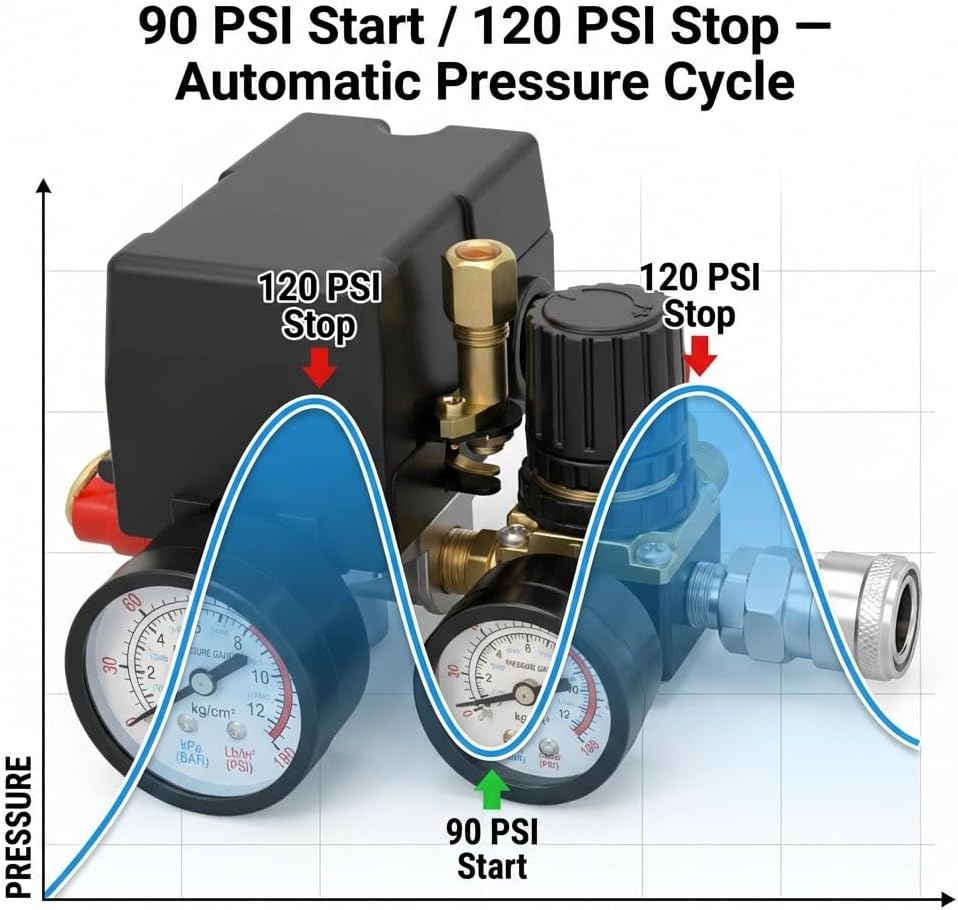
Image: Side view highlighting the pressure regulator knob. This knob allows for adjustment of the output air pressure.

Image: Side view showing the quick-connect coupler for attaching pneumatic tools.
4. Specifications
| Feature | Specification |
|---|---|
| Model Number | WD3785 |
| Brand | QWORK |
| Voltage | 240 Volts |
| Power Source | Corded Electric |
| Recommended Uses | Pressure Control in Air Compressor Systems |
| Thread Type | G1/4 BSP Female Thread |
| Compatibility | Suitable for single-phase or three-phase air compressor control systems. Not compatible with NPT-threaded compressors. |
| Max Working Pressure | 175 PSI |
| Pressure Switch Range | Cut-in 90 PSI, Cut-out 120 PSI |
| Recommended Compressor Power | 1-3 HP |
| Operating Temperature | 5°C–45°C (41°F–113°F) |
| Material Type | Acrylonitrile Butadiene Styrene (ABS) cover with iron fittings |
| Item Weight | 671 Grams |
| Special Feature | Precision Measurement, Portable |

Image: Product dimensions. This diagram provides key measurements of the pressure switch unit, useful for installation planning.
5. Setup and Installation
Proper installation is crucial for the safe and effective operation of your pressure switch. Always ensure the air compressor is unplugged and depressurized before beginning installation.
- Verify Compatibility: Confirm that your air compressor system uses G1/4 BSP threads. This unit is not compatible with NPT threads.
- Prepare Connections: Apply PTFE tape or thread sealant to all male threaded connections on the pressure switch and your compressor system to ensure a leak-free seal.
- Mount the Switch: Securely attach the pressure switch to the appropriate port on your air compressor. Ensure it is stable and free from excessive vibration.
- Connect Air Lines: Connect your air lines and pneumatic tools to the quick-connect coupler and other ports as needed.
- Electrical Wiring: Refer to the wiring diagram provided in Section 6 for correct electrical connections. If you are unsure, consult a qualified electrician.
- Leak Check: After installation, slowly repressurize the system and check all connections for air leaks using soapy water. Tighten any leaking connections.
Video: Air Compressor Pressure Switch Control Valve. This video provides a visual overview of the pressure switch, which may assist in understanding its components and installation points.
6. Wiring Diagram
The following diagram illustrates the internal wiring connections for the QWORK Air Compressor Pressure Switch. Ensure all electrical connections are made by a competent individual and comply with local electrical codes.

Image: Internal wiring diagram. This diagram shows the electrical connections within the pressure switch housing, including terminals for power input and motor connection.
7. Operating Instructions
Once installed and wired correctly, the pressure switch operates automatically to maintain your desired air pressure.
- Power On/Off: Use the red lever on the side of the switch to turn the compressor power ON or OFF.
- Automatic Pressure Cycle: The switch is factory-set to activate the compressor when pressure drops to 90 PSI and stop it when pressure reaches 120 PSI. This automatic cycle maintains a consistent pressure range.
- Regulator Adjustment: The black knob on the regulator allows you to adjust the output air pressure to your tools. Turn clockwise to increase pressure, counter-clockwise to decrease. Monitor the output gauge while adjusting.

Image: Automatic Pressure Cycle. This graph visually represents how the pressure switch maintains air pressure by starting the compressor at 90 PSI and stopping it at 120 PSI.
8. Maintenance
Regular maintenance helps ensure the longevity and reliable performance of your pressure switch.
- Inspect for Leaks: Periodically check all air connections for leaks. Tighten fittings or reapply thread sealant as needed.
- Clean Unit: Keep the exterior of the pressure switch clean and free from dust, dirt, and oil. Use a dry cloth for cleaning.
- Check Electrical Connections: Ensure all electrical wiring remains secure and free from corrosion.
- Environmental Check: Ensure the operating environment remains within the specified temperature and humidity ranges.
9. Troubleshooting
If you encounter issues with your QWORK Air Compressor Pressure Switch, refer to the following common troubleshooting steps:
- Compressor Not Starting:
- Check if the red ON/OFF lever is in the 'ON' position.
- Verify the power supply to the compressor.
- Ensure the tank pressure is below the 90 PSI cut-in threshold.
- Inspect electrical wiring for loose connections or damage.
- Compressor Not Stopping:
- Check if the tank pressure has reached the 120 PSI cut-out threshold.
- Listen for air leaks in the system, which could prevent pressure from building up.
- The pressure switch mechanism may be faulty; consider professional inspection.
- Air Leaks:
- Apply soapy water to all connections to identify the source of the leak.
- Tighten loose fittings.
- If necessary, disassemble, reapply PTFE tape, and reassemble the leaking connection.
- Inaccurate Pressure Readings:
- Ensure gauges are securely attached and not damaged.
- Compare readings with a known accurate pressure gauge if possible.
10. Warranty and Support
QWORK products are manufactured to high-quality standards. For warranty information, technical support, or assistance with parts, please contact QWORK customer service through the retailer where the product was purchased or visit the official QWORK website. Please have your model number (WD3785) and purchase date available when contacting support.