
Introduction
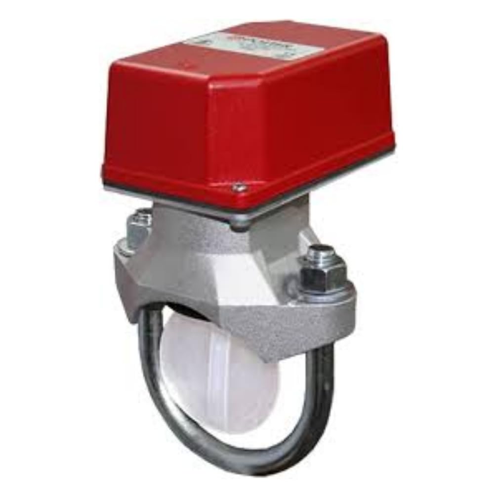
The POTTER VSR-3 is a vane type water flow alarm switch designed for use on 3-inch steel pipes. It is intended to detect a sustained flow of water in fire sprinkler systems, activating an alarm when flow conditions are met. This device is crucial for indicating the operation of sprinkler systems in the event of a fire.
Safety Information
Always adhere to local codes and regulations during installation and maintenance. Disconnect all power sources before servicing the device. Installation should only be performed by qualified personnel. Failure to follow these instructions could result in property damage, serious injury, or death.
- Ensure the system is depressurized before installation or removal.
- Wear appropriate personal protective equipment (PPE).
- Verify correct wiring to prevent electrical hazards.
Setup and Installation
The VSR-3 switch is designed for horizontal or vertical pipe installation. Ensure the arrow on the switch housing aligns with the direction of water flow.
1. Pre-installation Checks
- Confirm the pipe size is 3 inches.
- Inspect the switch for any damage.
- Ensure all necessary tools and materials are available.
2. Mounting Instructions
The VSR-3 mounts to the pipe using a saddle-type connection. A hole must be drilled into the pipe for the vane to be inserted.
- Depressurize and drain the pipe section where the switch will be installed.
- Drill a 1-1/4 inch (32 mm) hole in the pipe. Remove any burrs.
- Apply a suitable sealant to the saddle gasket.
- Position the saddle and switch assembly over the drilled hole, ensuring the flow arrow on the switch points in the direction of water flow.
- Secure the assembly with the provided U-bolt and nuts, tightening evenly to create a watertight seal. Do not overtighten.
3. Wiring Instructions
The VSR-3 contains two sets of SPDT (Single-Pole, Double-Throw) contacts. Refer to the wiring diagram inside the switch cover for specific connections.
- Connect the alarm circuit wiring to the appropriate terminals.
- Ensure all connections are secure and insulated.
- Verify that the electrical supply matches the switch's rating.
Operating Instructions
The VSR-3 is designed to activate an alarm when a sustained flow of water, equivalent to or greater than the flow from a single sprinkler head, occurs in the pipe. The time delay feature prevents false alarms due to pressure surges.
1. Alarm Activation
When water flows through the pipe and deflects the vane, the switch contacts change state after a preset time delay. This activates connected alarm devices (e.g., bells, panels).
2. Testing Procedures
Regular testing is essential to ensure proper operation. Follow NFPA 25 guidelines for inspection, testing, and maintenance of water-based fire protection systems.
- Weekly/Monthly: Visually inspect the switch for physical damage or corrosion.
- Quarterly/Annually: Conduct a full flow test by opening the inspector's test connection or a drain valve downstream of the switch. Verify that the alarm activates within the specified time delay (typically 5-90 seconds).
- Restore the system to normal operating conditions after testing.
Maintenance
The VSR-3 requires minimal maintenance. Regular inspections and functional testing are the primary maintenance activities.
- Keep the exterior of the switch clean and free from debris.
- Check for any signs of water leakage around the saddle connection.
- Ensure the conduit connections are tight and free from moisture.
- Do not attempt to lubricate or modify internal components.
Troubleshooting
| Problem | Possible Cause | Solution |
|---|---|---|
| No alarm during flow test | Incorrect wiring; Vane obstructed; Faulty switch; Insufficient flow | Check wiring connections; Inspect vane for obstructions; Replace switch if faulty; Ensure adequate water flow |
| False alarms | Water hammer/pressure surges; Improper time delay setting; Loose wiring | Adjust time delay (if applicable); Check for system pressure fluctuations; Secure wiring connections |
| Leakage at saddle connection | Improper tightening; Damaged gasket; Incorrect hole size | Retighten U-bolt nuts evenly; Replace gasket; Verify hole size and re-install |
Specifications
| Feature | Detail |
|---|---|
| Model Number | VSR-3 |
| Pipe Size Compatibility | 3 Inches |
| Inlet Connection Type | Flange (Saddle Mount) |
| Outlet Connection Type | NPT (for conduit) |
| Number of Ports | 1 |
| Electrical Contacts | 2 sets of SPDT |
| Manufacturer | POTTER |
| UPC | 767571885688 |
| Part Number | PVSR3 |
Warranty and Support
For warranty information and technical support, please contact POTTER directly or refer to the official documentation provided with your purchase. Keep your purchase receipt for warranty claims.
Contact Information: Refer to the manufacturer's official website or the packaging for the most current contact details.


