Introduction
This manual provides instructions for the safe operation and maintenance of the Proster Digital Multimeter 3999 and its accompanying 8-piece test lead set. Please read this manual thoroughly before using the device to ensure proper and safe operation.
Safety Information
General Safety Rules
- Always adhere to local and national safety codes.
- Do not exceed the maximum input values for any function.
- Use caution when working with voltages above 30V AC RMS, 42V peak, or 60V DC. These voltages pose a shock hazard.
- Before measuring current, ensure the circuit is de-energized and the multimeter is connected in series.
- Before measuring resistance or continuity, ensure the circuit is de-energized and all capacitors are discharged.
- Replace batteries when the low battery indicator appears.
- Do not operate the meter if it appears damaged or if the case is open.
- Keep fingers behind the probe barriers during measurements.
- Ensure the correct function and range are selected for the measurement.
- Always use the correct input terminals for the selected function.
Product Overview
Multimeter Components
The Proster Digital Multimeter 3999 features an LCD display, function selector dial, and input terminals for various electrical measurements.
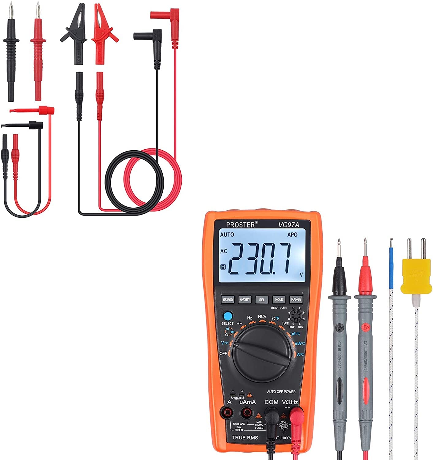
Overall view of the Proster Digital Multimeter 3999, showing its orange casing, LCD display, and rotary switch.
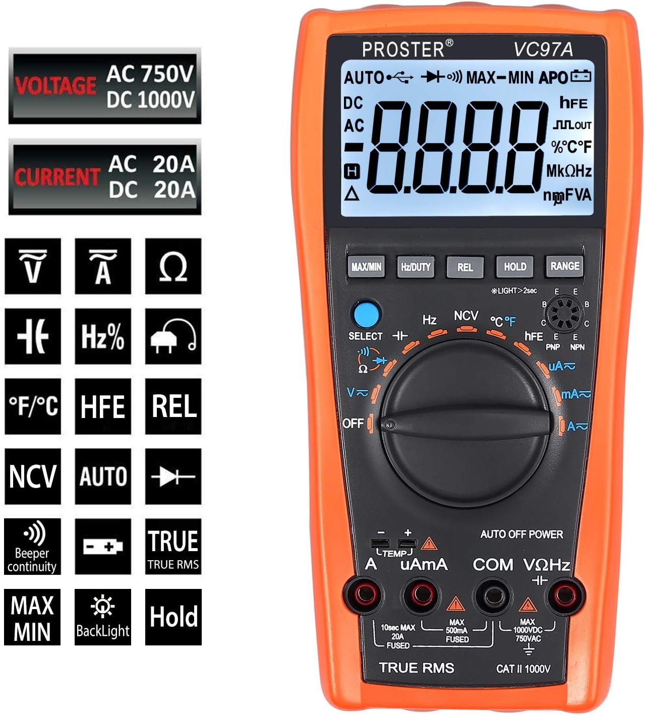
Detailed view of the multimeter's LCD display, function buttons (MAX/MIN, HZ/DUTY, REL, HOLD, RANGE), and rotary switch for selecting measurement modes.
Test Leads and Accessories
The included 8-piece test lead set provides versatility for various electrical measurements. All leads feature brass construction for durability and corrosion resistance.
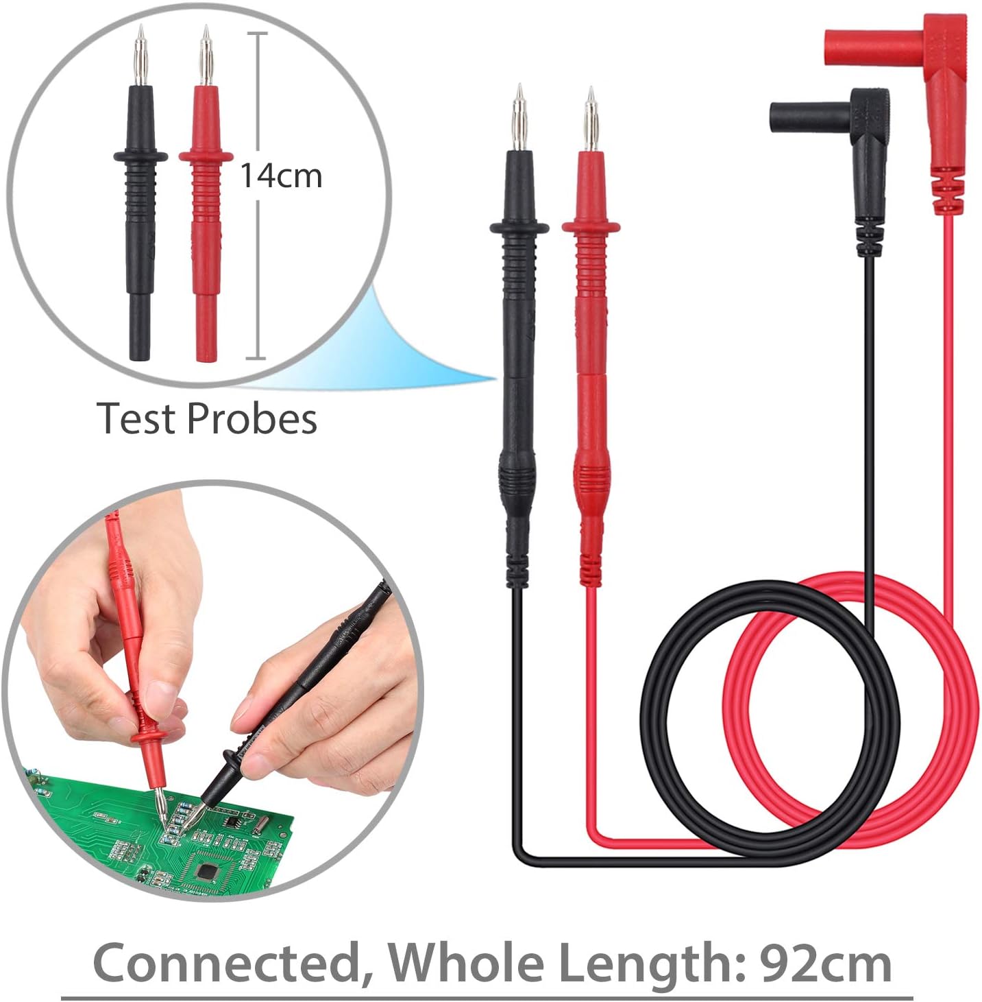
Standard test probes with 14cm length and a total connected length of 92cm. These are suitable for general purpose measurements.

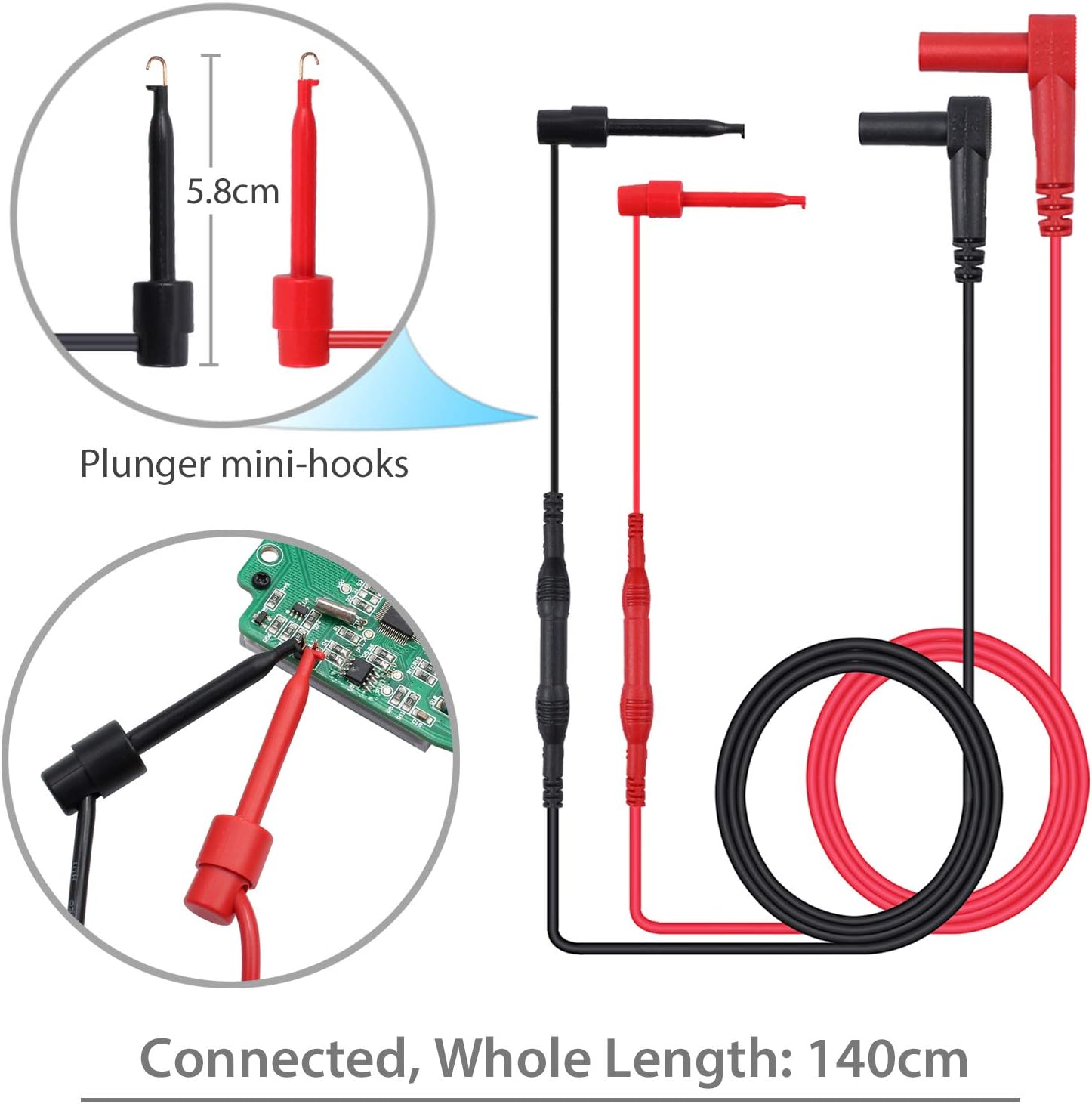
Plunger mini-hooks, 5.8cm in length, with a total connected length of 140cm. Ideal for connecting to small terminals or components.

Alligator clips, 9cm in length, with a total connected length of 90cm. Useful for hands-free connections to larger terminals or wires.
Setup
Battery Installation
- The multimeter requires two AAA batteries (included).
- Locate the battery compartment on the back of the multimeter.
- Use a screwdriver to open the battery cover.
- Insert the batteries, observing correct polarity (+ and -).
- Replace the battery cover and secure it with the screw.
Connecting Test Leads
- For most voltage, resistance, and continuity measurements, connect the red test lead to the "VΩHz" terminal and the black test lead to the "COM" terminal.
- For current measurements, connect the red test lead to the "uAmA" terminal (for micro/milli-amps) or the "A" terminal (for amps) and the black test lead to the "COM" terminal.
- Ensure test leads are fully inserted into the correct terminals.
Operating Instructions
Power On/Off
- Turn the rotary switch from "OFF" to any desired function to power on the multimeter.
- To power off, turn the rotary switch back to "OFF". The multimeter also features an Auto Power Off (APO) function to conserve battery life.
Function Selection
- Rotate the central dial to select the desired measurement function (e.g., V~ for AC Voltage, V- for DC Voltage, Ω for Resistance, A~ for AC Current, A- for DC Current, Hz for Frequency, °C/°F for Temperature).
- Use the "SELECT" button to toggle between different modes within a single dial position (e.g., AC/DC voltage, resistance/continuity).
Measuring Voltage (AC/DC)
- Connect the red test lead to the "VΩHz" terminal and the black test lead to the "COM" terminal.
- Turn the rotary switch to V~ (AC Voltage) or V- (DC Voltage). Use the "SELECT" button if needed.
- Connect the test probes in parallel with the circuit or component to be measured.
- Read the voltage value on the LCD display.
Measuring Current (AC/DC)
- WARNING: Ensure the circuit is de-energized before connecting the multimeter for current measurement.
- Connect the black test lead to the "COM" terminal.
- For micro/milli-amps, connect the red test lead to the "uAmA" terminal. For amps, connect the red test lead to the "A" terminal.
- Turn the rotary switch to A~ (AC Current) or A- (DC Current). Use the "SELECT" button if needed.
- Open the circuit and connect the multimeter in series with the load.
- Re-energize the circuit and read the current value.
Measuring Resistance
- WARNING: Ensure the circuit is de-energized and all capacitors are discharged before measuring resistance.
- Connect the red test lead to the "VΩHz" terminal and the black test lead to the "COM" terminal.
- Turn the rotary switch to Ω (Resistance).
- Connect the test probes across the component to be measured.
- Read the resistance value on the LCD display.
Continuity Test
- WARNING: Ensure the circuit is de-energized before performing a continuity test.
- Connect the red test lead to the "VΩHz" terminal and the black test lead to the "COM" terminal.
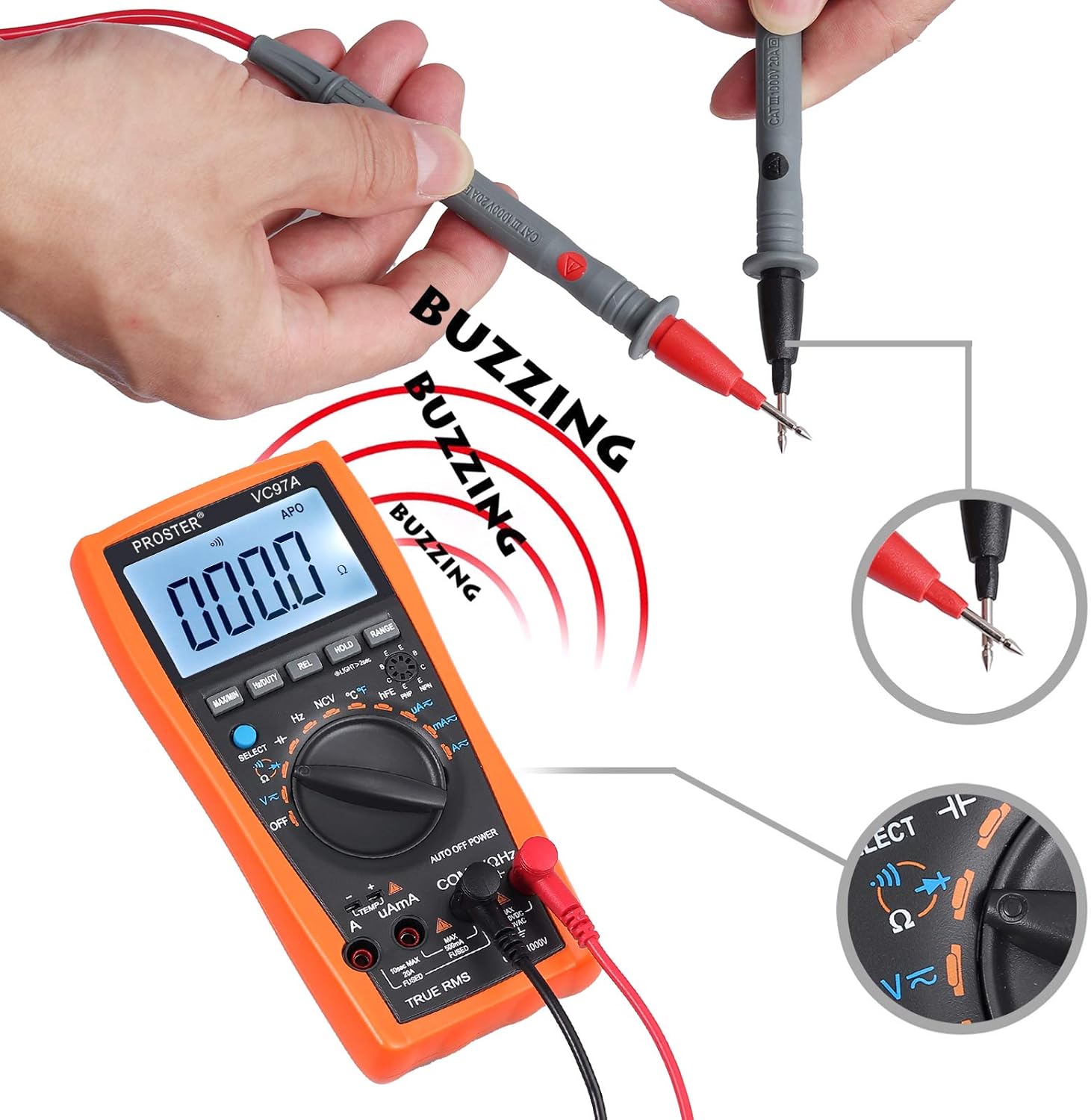
- Turn the rotary switch to the continuity symbol (speaker icon).
- Connect the test probes across the circuit or component.
- A continuous beep indicates a complete circuit (low resistance). The display will show the resistance value.
Performing a continuity test. The multimeter emits a buzzing sound when a continuous circuit is detected, indicating low resistance.
Measuring Temperature
- Connect the K-type temperature probe (included) to the multimeter's input terminals, observing polarity.
- Turn the rotary switch to °C/°F.
- Place the temperature probe in the environment or on the object to be measured.
- Read the temperature value on the LCD display.

Measuring the surrounding air temperature using the K-type temperature probe.
Measuring the temperature of a liquid using the K-type temperature probe.
Special Functions
- MAX/MIN: Press to display the maximum or minimum measured value.
- HOLD: Press to freeze the current reading on the display.
- REL (Relative Measurement): Press to store the current reading as a reference and display subsequent measurements as a deviation from this reference.
- RANGE: For manual ranging (if auto-ranging is not desired or available for a specific function).
- Backlight: Press the backlight button (often combined with HOLD or another button) to illuminate the display in low-light conditions.
- NCV (Non-Contact Voltage): Allows detection of AC voltage without direct contact. Select NCV mode and bring the top of the multimeter near an AC voltage source.
Maintenance
Battery Replacement
When the low battery indicator appears on the display, replace the batteries as described in the "Battery Installation" section.
Cleaning
- Wipe the multimeter case with a damp cloth and mild detergent. Do not use abrasives or solvents.
- Ensure the device is powered off and test leads are disconnected before cleaning.
Storage
- If the multimeter is not used for an extended period, remove the batteries to prevent leakage.
- Store the device in a cool, dry place, away from direct sunlight and extreme temperatures.
Troubleshooting
No Display / Power On Issue
- Check battery installation and polarity.
- Replace batteries if they are low or depleted.
- Ensure the rotary switch is turned to an active function, not "OFF".
Incorrect Readings
- Verify the correct function and range are selected.
- Ensure test leads are properly connected to the correct input terminals.
- Check for damaged test leads or probes.
- Ensure the circuit is de-energized for resistance/continuity measurements.
Overload Indication ("OL")
- The measured value exceeds the selected range. Switch to a higher range or verify the circuit conditions.
No Continuity Beep
- Ensure the circuit is de-energized.
- Check for an open circuit or high resistance.
- Verify test lead connections.
Specifications
- Display: LCD, 3999 counts
- DC Voltage: Up to 1000V
- AC Voltage: Up to 750V
- DC Current: Up to 20A
- AC Current: Up to 20A
- Resistance: Yes
- Capacitance: Up to 200uF
- Frequency: Yes
- Duty Cycle: Yes
- Temperature: Yes (K-type probe included)
- Continuity: Yes (with buzzer)
- Diode Test: Yes
- NCV (Non-Contact Voltage): Yes
- Special Features: Low Battery Voltage Indication, Overload Protection, Auto Power Off, Data Hold, MAX/MIN, Relative Measurement, Backlight.
- Power Source: 2 x AAA batteries
- Safety Rating: CAT II 1000V
Warranty and Support
For warranty information or technical support, please refer to the product packaging or contact Proster customer service directly. Contact details are typically available on the manufacturer's website or included documentation.


