
Introduction
This manual provides detailed instructions for the installation, operation, and maintenance of your JBL Club A5055 5-channel amplifier. Please read this manual thoroughly before attempting installation or operation to ensure proper use and to prevent damage.
The JBL Club A5055 is designed to deliver powerful audio performance, providing 50 Watts RMS x 4 channels for front and rear speakers, and 500 Watts RMS x 1 channel for a subwoofer. It features a compact design, low noise and distortion, variable crossovers, bass boost, and a wired remote bass control.
What's in the Box
Verify that all components are present before installation:
- One Club A5055 five-channel amplifier
- Four Bare wire-to-RCA adapters
- Six 30A ATO fuses (3 installed, 3 spare)
- Remote bass control module
- 16.5’ Remote control cable (RJ-25 plugs on both ends)
- Two Self-tapping screws for remote (M3 x 15mm)
- Four Mounting screws (M4 x 53mm)
- Owner’s Manual
- Two JBL stickers
- One logo badge
Setup and Installation
Proper installation is crucial for optimal performance and safety. If you are unsure about any part of the installation process, consult a qualified professional.
Mounting the Amplifier
Choose a mounting location that provides adequate ventilation and protects the amplifier from moisture and direct sunlight. Ensure the mounting surface is sturdy.
- Mark the mounting holes using the amplifier as a template.
- Drill pilot holes.
- Secure the amplifier using the provided mounting screws.

Image: Top view of the JBL Club A5055 amplifier, showing its compact design.
Wiring Connections
Before making any connections, disconnect the vehicle's negative battery terminal to prevent electrical shorts.
Power and Ground Connections
Use 4-gauge power and ground leads (not included).
- Connect the power cable to the +12V terminal on the amplifier and to the positive terminal of the vehicle's battery via an appropriate fuse (not included).
- Connect the ground cable to the GND terminal on the amplifier and to a clean, unpainted metal surface of the vehicle's chassis.
- Connect the remote turn-on wire from your head unit to the REM terminal on the amplifier.
Audio Input Connections
The amplifier supports both low-level (RCA) and high-level (speaker wire) inputs.
Low-Level Input (RCA)
- Connect RCA cables from your head unit's pre-outs to the FRONT, REAR, and SUB RCA inputs on the amplifier.
High-Level Input (Speaker Wire)
- If your head unit does not have RCA outputs, use the provided bare wire-to-RCA adapters.
- Connect your head unit's speaker outputs to the adapters, then plug the adapters into the amplifier's RCA inputs.
Speaker Output Connections
- Connect your front speakers to the FRONT speaker terminals.
- Connect your rear speakers to the REAR speaker terminals.
- Connect your subwoofer to the SUB speaker terminals.
- For bridged mode (3-channel operation), refer to the specific wiring diagram for 140W RMS x 2 + 500W RMS x 1.

Image: Rear panel of the JBL Club A5055 amplifier, showing RCA inputs, speaker terminals, power connections, and fuse slots.
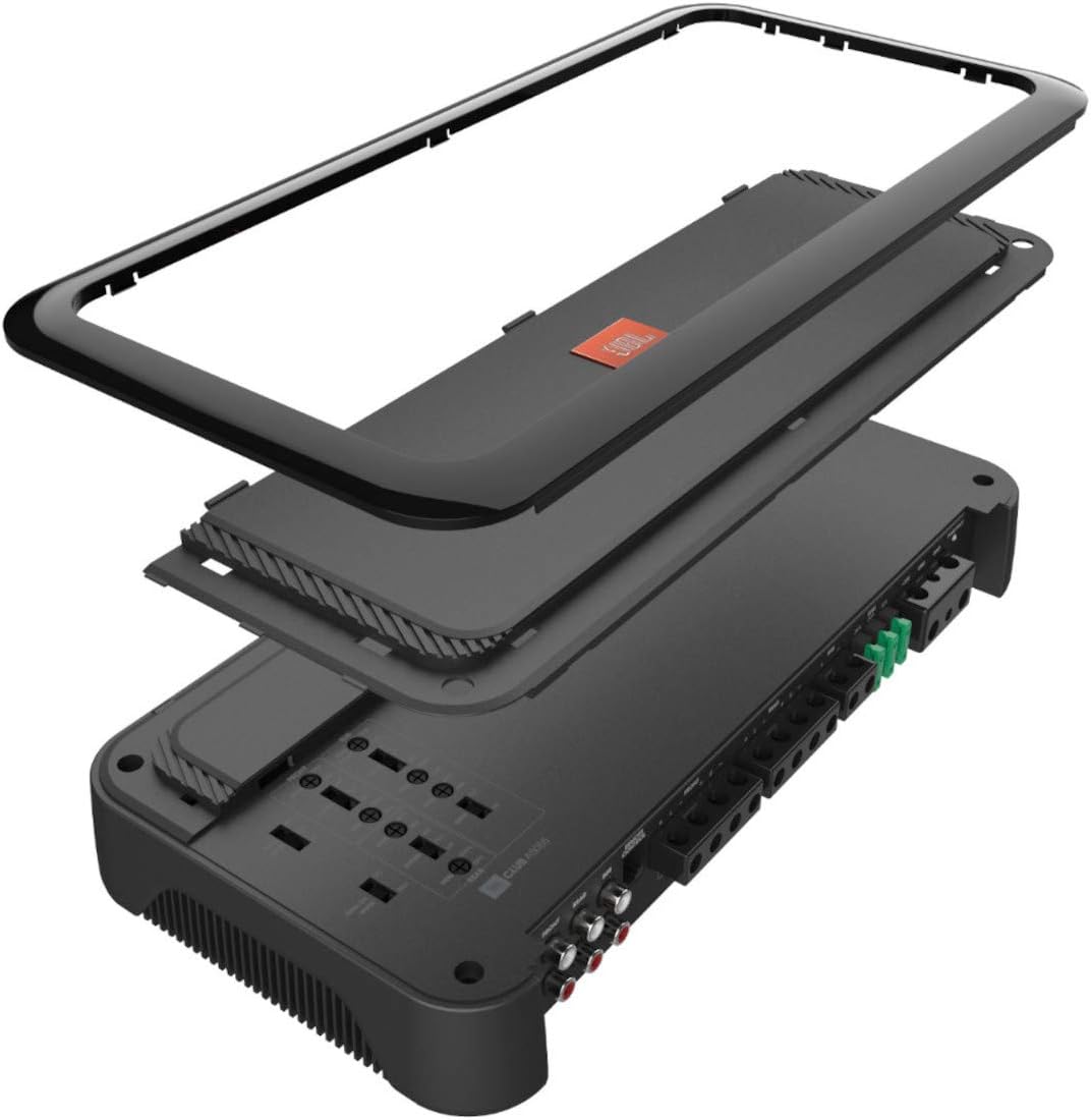
Image: Exploded view of the JBL Club A5055 amplifier, illustrating its internal components and layered design.
Operating Instructions
Controls and Adjustments
The JBL Club A5055 amplifier features various controls to fine-tune your audio system.
Gain Control
Adjust the gain control for each channel (Front, Rear, Sub) to match the output level of your head unit. Start with the gain at minimum and slowly increase it until you hear distortion, then back off slightly.
Crossover Settings
The front and rear channels have variable high-pass and low-pass filters (32-320 Hz, 12 dB/octave). The subwoofer channel has a variable low-pass filter (32-320 Hz, 12 dB/octave).
- High-Pass Filter (HPF): Allows frequencies above the set point to pass through. Use for full-range speakers to prevent low frequencies from distorting them.
- Low-Pass Filter (LPF): Allows frequencies below the set point to pass through. Use for subwoofers to prevent high frequencies from playing.
Bass Boost
The subwoofer channel features a variable bass boost (0-12 dB at 45 Hz) to enhance low-frequency output. Use sparingly to avoid distortion.
Phase Switch
The subwoofer channel includes a phase switch (0, 180 degrees) to optimize subwoofer performance relative to your main speakers. Experiment with both settings to find the one that provides the most impactful bass.
Wired Remote Bass Control
Connect the wired remote bass control module to the "REMOTE CONTROL" port on the amplifier. This allows convenient adjustment of the subwoofer level from the driver's seat.
Maintenance
- Keep the amplifier clean and free from dust. Use a soft, dry cloth for cleaning.
- Ensure adequate ventilation around the amplifier to prevent overheating. Do not block cooling fins.
- Periodically check all wiring connections for tightness and corrosion.
- Replace fuses only with the same type and rating (30A ATO).
Troubleshooting
| Problem | Possible Cause | Solution |
|---|---|---|
| No Power | Blown fuse; Loose power/ground connection; No remote turn-on signal. | Check/replace fuses; Verify all power and ground connections are secure; Check remote wire connection and head unit output. |
| No Sound | Input cables disconnected; Speaker wires disconnected; Gain too low; Crossover settings incorrect. | Check RCA/speaker input connections; Verify speaker wire connections; Adjust gain; Review crossover settings. |
| Distorted Sound | Gain set too high; Incorrect crossover settings; Speaker impedance mismatch. | Reduce gain; Adjust crossover settings; Ensure speakers are compatible with amplifier impedance. |
| Amplifier Overheats (Shuts Off) | Insufficient ventilation; Low impedance load; Prolonged high-volume use. | Ensure proper airflow around amplifier; Check speaker impedance; Reduce volume or allow cooling time. |
Technical Specifications
| Feature | Specification |
|---|---|
| Model Name | CLUB A5055 |
| Model Number | AMPCBA5055AM |
| Channels | 5 |
| Power Output (RMS, 4 Ohms) | 50W x 4 + 320W x 1 |
| Power Output (RMS, 2 Ohms) | 65W x 4 + 500W x 1 |
| Bridged Power Output (RMS, 4 Ohms) | 140W x 2 + 500W x 1 |
| Frequency Response | 20 Hz - 20 kHz |
| High-Pass Filter (Front/Rear) | Variable, 32-320 Hz, 12 dB/octave |
| Low-Pass Filter (Front/Rear/Sub) | Variable, 32-320 Hz, 12 dB/octave |
| Bass Boost (Subwoofer) | 0-12 dB at 45 Hz |
| Phase Switch (Subwoofer) | 0, 180 degrees |
| Fuse Rating | 30A x 3 |
| Dimensions (W x H x D) | 14-1/8" x 2" x 7" (approximate) |
| Input Voltage | 12 volts |
| Connectivity Technology | Wired |
| Audio Output Mode | Surround |
| Enclosure Material | Plastic, Polypropylene |

Image: Diagram showing the dimensions of the JBL Club A5055 amplifier: 14.96" length, 8.94" width, and 4.45" height.
Warranty Information
This JBL Club A5055 amplifier comes with a 1-year manufacturer's limited warranty. This warranty covers defects in materials and workmanship under normal use. It does not cover damage resulting from misuse, accident, modification, or unauthorized repair.
Please retain your proof of purchase for warranty claims. For full warranty terms and conditions, refer to the official JBL website or contact customer support.
Customer Support
For technical assistance, troubleshooting, or warranty inquiries, please contact JBL customer support.
- Website: Visit the official JBL website for support resources, FAQs, and contact information.
- Phone: Refer to the JBL website for regional customer service phone numbers.
When contacting support, please have your product model (CLUB A5055) and serial number available.


