1. Introduction
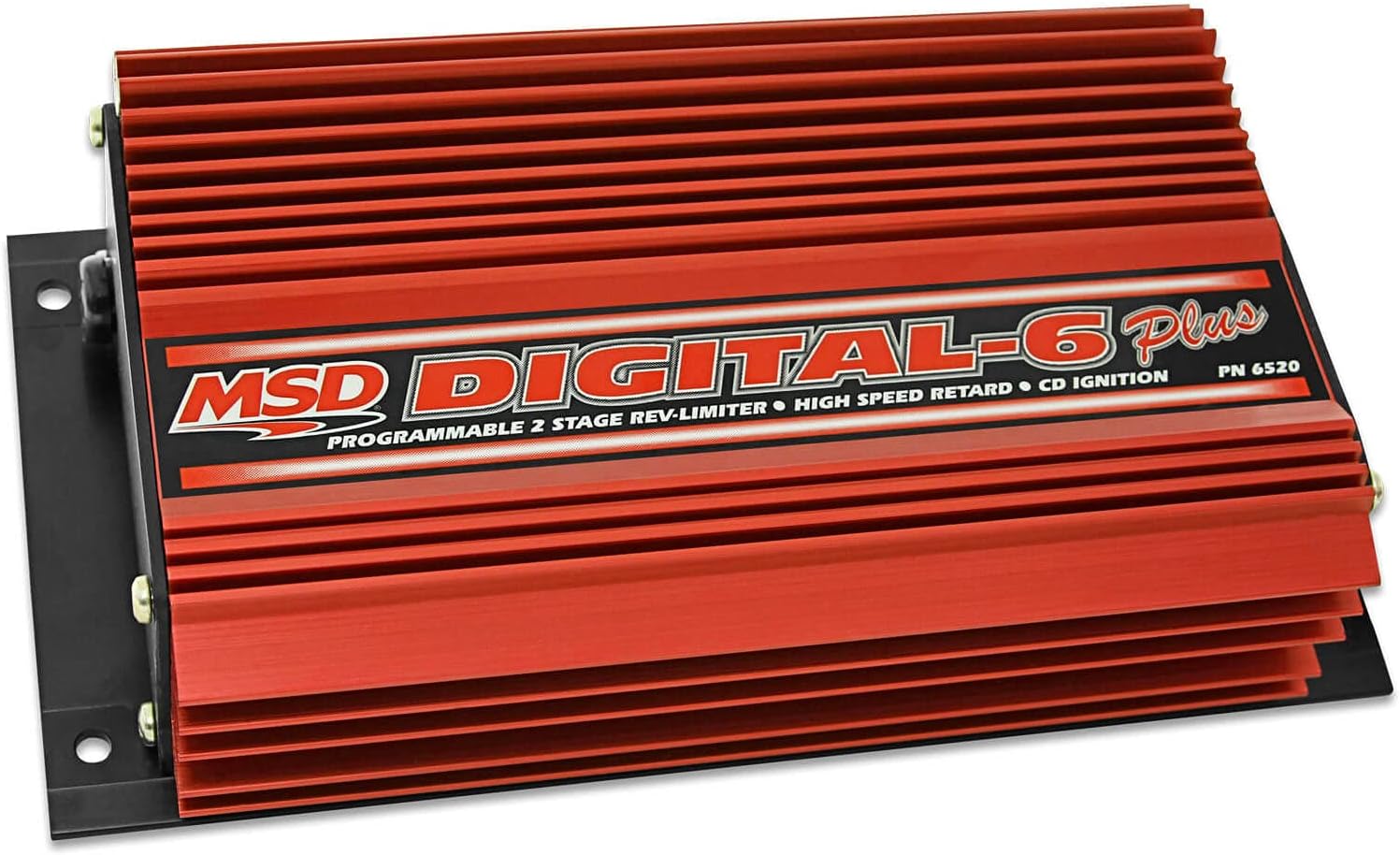
The MSD Digital 6-Plus Ignition Control is an advanced ignition system designed for automotive applications. It integrates digital accuracy with robust power delivery, making it suitable for various engine configurations. This unit utilizes a high-speed RISC microcontroller to precisely manage ignition output, analyze input signals, and maintain accurate timing and RPM limits. Its design incorporates protection against Electro-Magnetic Interference (EMI) for reliable performance.
2. Key Features
- Dual Rev Limits: Allows switching between two distinct rev limits, adjustable in 100 RPM increments using rotary switches.
- Single Stage Retard: Provides a single stage of timing retard, beneficial for applications such as nitrous oxide systems or specific top-end performance tuning.
- Start Retard Function: Reduces timing during engine cranking to ease strain on the starter motor, flywheel, and engine components.
- Adjustable Magnetic Pickup Compensation: Ensures accurate trigger signals from magnetic pickups, optimizing ignition timing precision.
- Diagnostic LED Display: An integrated LED provides warnings for trigger signal issues or potential faults within the vehicle's charging system.
- High Spark Energy: Delivers 135 millijoules of spark energy and 535 primary volts per spark.
- Versatile Input Compatibility: Compatible with points, amplifier, and magnetic pickup trigger inputs.
- Engine Compatibility: Operates with 4, 6, or 8-cylinder engines.
3. Package Contents
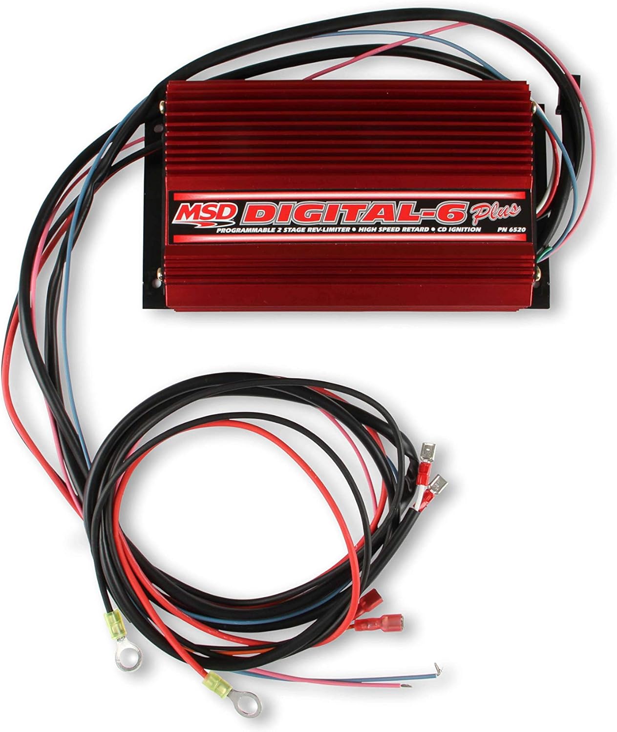
Verify that all components listed below are present in your package before beginning installation.

- MSD 6520 Digital 6-Plus Ignition Control Unit
- Main Wiring Harness (power, ground, coil, trigger wires)
- Magnetic Pickup Wiring Harness
- Small Parts Kit (includes various terminals, connectors, screws, nuts, zip ties, rotary switches for rev limits, and an adjustment tool)
4. Installation Guidelines
4.1 Mounting the Unit
Select a mounting location that is away from direct engine heat, exhaust components, and excessive vibration. Ensure the location allows for proper ventilation and access to wiring. Use the provided mounting hardware to secure the unit firmly.
4.2 Wiring Connections
Refer to the detailed wiring diagram provided in the complete installation manual for specific connections. General connections include:
- Power (Red Wire): Connect directly to the positive terminal of the battery.
- Ground (Black Wire): Connect to a clean, chassis ground point.
- Coil Connections: Connect the orange wire to the positive terminal of the ignition coil and the black wire to the negative terminal of the ignition coil.
- Trigger Input: Connect the appropriate trigger wires (e.g., magnetic pickup, points, or amplifier output) to the designated input terminals on the MSD unit.
- Tachometer Output: Connect the gray wire to the tachometer signal input.


5. Operating Instructions
5.1 Setting Rev Limits
The Digital 6-Plus features two adjustable rev limits. These are typically set using rotary switches located on the unit or via external controls. Consult the full manual for precise adjustment procedures. Each limit can be set in 100 RPM increments.

5.2 Activating Timing Retard
The single-stage timing retard function is typically activated by an external switch or signal, such as from a nitrous system. Refer to the wiring diagram for connecting the retard activation wire.
5.3 Diagnostic LED
Observe the diagnostic LED on the unit. It provides visual indications of potential issues, such as trigger signal problems or faults within the vehicle's charging system. Refer to the troubleshooting section for interpreting LED codes.
6. Maintenance
The MSD 6520 Digital 6-Plus Ignition Control is designed for minimal maintenance. Periodically inspect all wiring connections for tightness and corrosion. Ensure the unit's mounting remains secure and that it is free from debris or excessive heat buildup. No user-serviceable parts are inside the sealed unit.
7. Troubleshooting
This section addresses common issues that may arise during the operation of your MSD 6520 unit.
7.1 Engine Not Starting or Misfiring
- Check Power and Ground: Ensure the red wire has a constant 12V supply and the black wire has a solid chassis ground.
- Verify Coil Connections: Confirm the orange and black coil wires are correctly connected to the ignition coil terminals.
- Inspect Trigger Input: Ensure the trigger wires (e.g., magnetic pickup) are securely connected and providing a clean signal.
- Diagnostic LED: Check the LED for any error indications related to trigger signals.
7.2 Incorrect Rev Limit Operation
- Verify Rotary Switch Settings: Double-check the positions of the rotary switches for the desired RPM limits.
- Confirm Activation: If using a switchable rev limit, ensure the activation switch is functioning correctly.
7.3 Charging System Warning (LED Indication)
- If the diagnostic LED indicates a charging system issue, inspect the vehicle's alternator, battery, and associated wiring. The MSD unit can detect voltage irregularities.
8. Technical Specifications
| Specification | Value |
|---|---|
| Model Number | 6520 |
| Manufacturer | MSD |
| Item Weight | 4.8 pounds |
| Product Dimensions | 11 x 8 x 3 inches |
| Exterior Finish | Machined |
| Spark Energy | 135 mJ |
| Primary Voltage | 535 Volts |
| Engine Compatibility | 4, 6, or 8-cylinder |
| Rev Limit Adjustment | 100 RPM increments |
9. Warranty and Support
For detailed warranty information, product registration, and technical support, please refer to the official MSD website or contact their customer service directly. Keep your purchase receipt for warranty claims.


