1. Introduction and Overview
The Klein Tools CL320 is an advanced, auto-ranging True Root Mean Square (TRMS) digital clamp meter designed for professional use in HVAC and electrical applications. It provides comprehensive measurement capabilities including AC current via the clamp, AC/DC voltage, DC microamps, resistance, continuity, frequency, capacitance, and diode testing using test leads, as well as temperature measurement with a thermocouple probe. Its auto-ranging feature enhances efficiency, while the backlit display ensures clear readings in various lighting conditions.

Figure 1.1: Klein Tools CL320 Digital Clamp Meter and included accessories.
2. Safety Information
Always adhere to local and national safety codes. Use personal protective equipment (PPE) to prevent shock and arc blast injury where hazardous live conductors are exposed. This meter is designed for use in CAT III 600V and CAT IV 600V environments. Ensure test leads are in good condition and have CAT III/CAT IV safety caps. Do not use the meter if it appears damaged or if the battery door is not fully closed. Refer to the official Instructions for Use (IFU) PDF for detailed safety warnings and precautions.
- DO NOT use the meter on circuits exceeding its specified voltage or current ratings.
- DO NOT use the meter during electrical storms or in wet weather.
- ALWAYS disconnect power to the circuit before making resistance, continuity, capacitance, or diode measurements.
- ENSURE the meter is in the correct function and range before making measurements.
- BE AWARE of the risk of electric shock. Voltages above 30V AC RMS, 42V peak, or 60V DC are considered hazardous.
3. Package Contents
Verify that all items listed below are present in your package:
- Klein Tools CL320 Digital Clamp Meter
- Carrying Case
- Test Leads with CAT III/CAT IV Safety Caps (Red and Black)
- Thermocouple Probe
- 3 x AAA Batteries (pre-installed or separate)
- Instructions Manual (this document)
4. Product Features
The CL320 Digital Clamp Meter offers a robust set of features for accurate and versatile electrical measurements:
- Auto-Ranging: Automatically selects the correct measurement range.
- True Root Mean Square (TRMS): Provides accurate readings for non-sinusoidal waveforms.
- AC Current Measurement: Up to 400A via the clamp jaw.
- AC/DC Voltage Measurement: Measures voltage via test leads.
- DC Microamps: Essential for flame sensor testing.
- Resistance: Measures electrical resistance.
- Continuity: Audible indication for circuit continuity.
- Frequency/Duty Cycle: Measures signal frequency and duty cycle.
- Capacitance: Measures capacitance of components.
- Diode Test: Checks the functionality of diodes.
- Temperature: Measures temperature using the included thermocouple.
- Non-Contact Voltage Testing (NCVT): Integrated into the clamp jaw for quick voltage detection.
- Backlit Display: LCD screen with backlight for improved visibility in low-light conditions.
- Max/Min Function: Records maximum and minimum readings during a measurement session.
- Data Hold: Freezes the current reading on the display.
- Auto-Power Off: Conserves battery life by automatically shutting off after 10 minutes of inactivity.
- Test Lead Holder: Conveniently located on the side of the clamp.

Figure 4.1: Key features and specifications of the CL320.
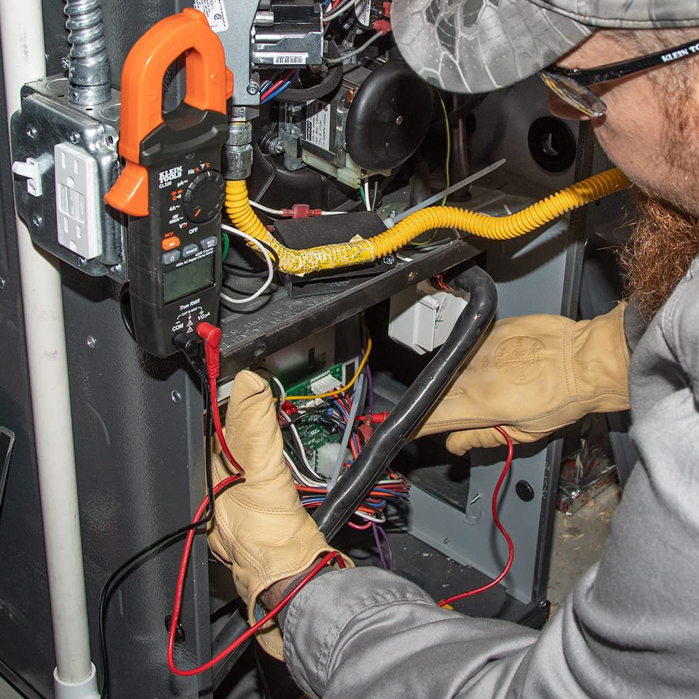
Figure 4.2: Integrated test lead holder for convenience.
5. Setup
5.1 Battery Installation
The CL320 requires three (3) AAA batteries. These may be pre-installed. If not, or if replacement is needed:
- Ensure the meter is OFF.
- Locate the battery compartment on the back of the meter.
- Use a screwdriver to open the battery compartment cover.
- Insert the AAA batteries, observing the correct polarity (+/-) as indicated inside the compartment.
- Replace the battery compartment cover and secure it with the screw.

Figure 5.1: Back view of the CL320, indicating the battery compartment.
5.2 Connecting Test Leads
For most measurements (voltage, resistance, continuity, etc.), the test leads must be connected:
- Insert the black test lead into the COM (common) input jack.
- Insert the red test lead into the VΩµA input jack.
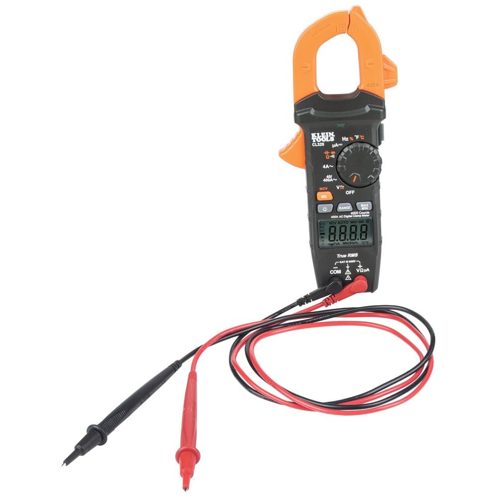
Figure 5.2: Front view of the CL320 with input jacks for test leads.
6. Operating Instructions
Turn the function selector dial to the desired measurement setting. The meter will automatically range for most measurements. Press the 'SEL' button to toggle between AC/DC or other sub-functions where applicable.
6.1 AC Current Measurement (Clamp)
To measure AC current, rotate the dial to the 40A~ or 400A~ position. Open the clamp jaw and enclose only one conductor. The reading will appear on the display.

Figure 6.1: Measuring AC current using the clamp function.
6.2 AC/DC Voltage Measurement
Connect test leads as described in Section 5.2. Rotate the dial to the V~ (AC Voltage) or V- (DC Voltage) position. If the dial has a combined V setting, press 'SEL' to switch between AC and DC. Apply the test probes to the circuit points to be measured.
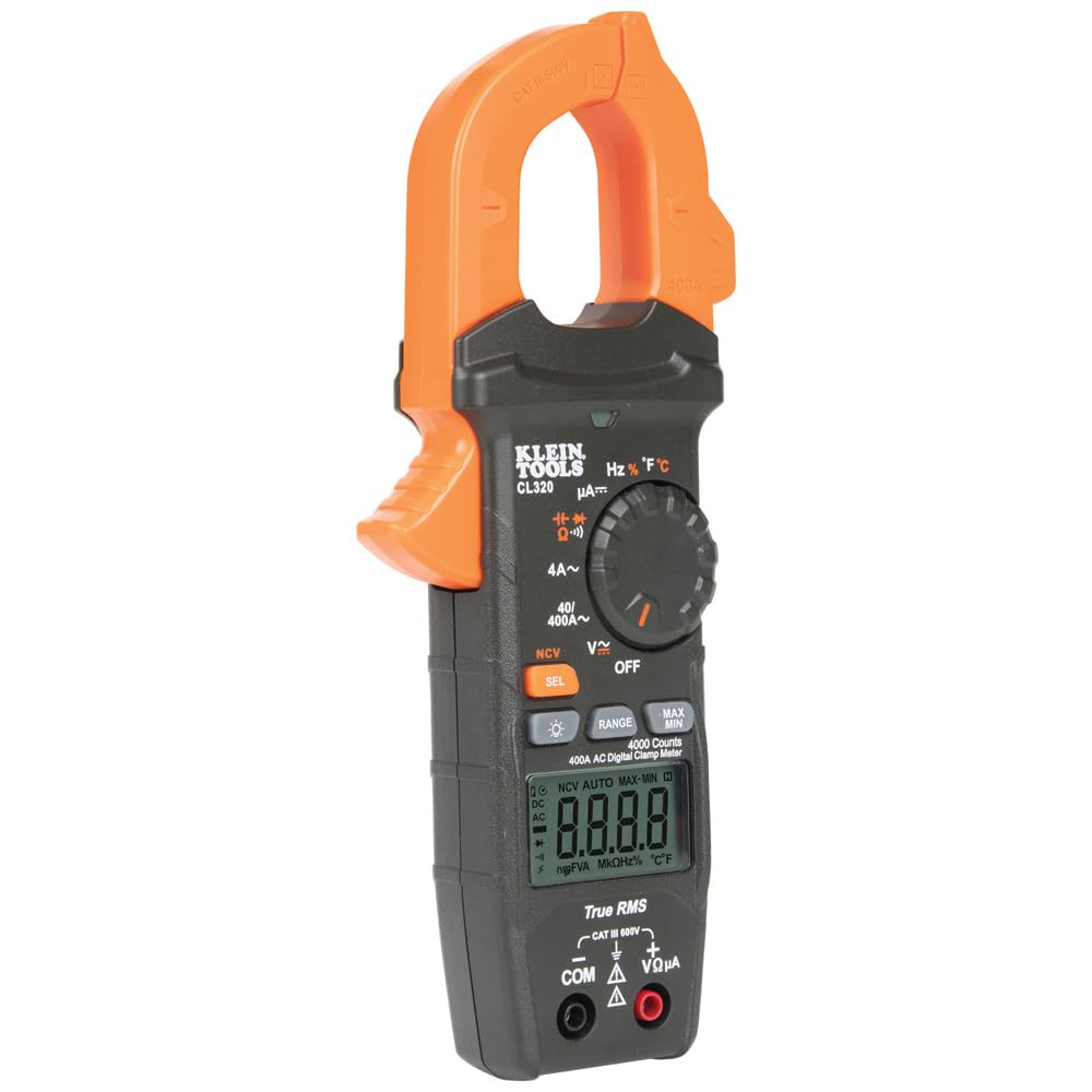
Figure 6.2: Measuring voltage with test leads.
6.3 Resistance, Continuity, Capacitance, Diode Test
Connect test leads. Rotate the dial to the Ω (Resistance),  (Continuity), (Capacitance), or (Diode) position. Press 'SEL' to cycle through these functions if they share a dial position. Apply probes to the de-energized circuit or component.
6.4 DC Microamps Measurement
Connect test leads. Rotate the dial to the µA- position. This function is typically used for sensitive measurements like flame sensor current. Ensure the circuit is de-energized before connecting the meter in series.
6.5 Temperature Measurement
Connect the thermocouple probe to the meter's input jacks, observing polarity. Rotate the dial to the °F/°C position. The display will show the temperature. Press 'SEL' to switch between Fahrenheit and Celsius.
6.6 Non-Contact Voltage Testing (NCVT)
Rotate the dial to the NCV position. Hold the tip of the clamp jaw near a live AC voltage source. The meter will emit an audible beep and the NCV indicator light will illuminate when voltage is detected.
6.7 Max/Min and Data Hold Functions
- Max/Min: Press the 'MAX/MIN' button to activate. The meter will record the highest and lowest readings. Press again to cycle between MAX, MIN, and current reading.
- Data Hold: Press the 'HOLD' button to freeze the current reading on the display. Press again to release.
6.8 Backlit Display
Press the backlight button (light bulb icon) to illuminate the display for better visibility in dark environments. Press again to turn off.

Figure 6.3: The CL320's backlit display for low-light conditions.
7. Maintenance
7.1 Cleaning
Ensure the meter is turned OFF and disconnected from any circuit. Wipe the meter with a clean, dry, lint-free cloth. Do not use abrasive cleaners or solvents. The clamp jaw area should be kept clean to ensure proper operation.
7.2 Battery Replacement
When the low battery indicator appears on the display, replace the batteries as described in Section 5.1. Prompt battery replacement ensures accurate readings and proper meter function.
7.3 Storage
When not in use for extended periods, store the meter in its carrying case in a cool, dry environment, away from direct sunlight and extreme temperatures. Remove batteries if storing for more than a month to prevent leakage.
8. Troubleshooting
| Problem | Possible Cause | Solution |
|---|---|---|
| No display / Meter won't turn on | Dead or incorrectly installed batteries | Replace batteries; check polarity. |
| Inaccurate readings | Incorrect function/range selected; dirty test leads/jacks; external interference | Verify dial setting; clean contacts; move away from strong electromagnetic fields. |
| Continuity buzzer not working | Circuit resistance too high; meter not in continuity mode | Ensure circuit is below 30Ω; select continuity mode. |
| NCVT not detecting voltage | Voltage too low; NCVT sensor not close enough to source | Ensure voltage is within detectable range; position sensor directly over live conductor. |
9. Specifications
| Specification | Value |
|---|---|
| Model Number | CL320 |
| Product Dimensions | 8.45 x 3.51 x 1.51 inches |
| Item Weight | 0.62 Pounds (9.92 ounces) |
| Power Source | Battery Powered (3 x AAA) |
| Color | Black/Orange |
| AC Current Range | Up to 400A |
| Voltage Rating | CAT III 600V, CAT IV 600V |
| Display | 4000 Counts, Backlit LCD |
| Auto-Power Off | Yes, after 10 minutes |
10. Warranty and Support
Klein Tools products are manufactured to high standards of quality and durability. For specific warranty information, please refer to the official documentation included with your product or visit the Klein Tools website. For technical support, product inquiries, or to access the full Instructions for Use (IFU) PDF, please visit the official Klein Tools store or contact their customer service.
Official Instructions for Use (IFU) PDF: Download PDF
Visit the KLEIN TOOLS Store: KLEIN TOOLS Store on Amazon
Note: No official product videos with verifiable creator information were provided in the source data to be embedded.


