1. Introduction
This manual provides detailed instructions for the installation, operation, and maintenance of the ATO Compression Load Cell, 2 Ton. The ATO Compression Load Cell is a transducer designed to convert mechanical force into an electrical signal. It is widely used in industrial automation, weighing systems, force measurement, and control applications, providing accurate and reliable solutions for tension, compression, or multi-axis force measurement.

Image 1.1: Top-down view of the ATO Compression Load Cell, 2 Ton. This image shows the robust stainless steel construction and the central loading point.
2. Product Features
- Material: Constructed from durable alloy steel or stainless steel for longevity and resistance to environmental factors.
- Function: Specifically designed for precise weight measurement, offering good anti-eccentric load performance and a low-profile design.
- Sealing: Features a fully sealed construction, enhancing durability and protection in various industrial environments.
- Accuracy: Achieves an accuracy of 0.03% F.S (Full Scale), encompassing linearity, hysteresis, and repeatability.
- Protection Class: Rated IP67, indicating complete protection against dust ingress and temporary immersion in water.
3. Applications
The ATO Compression Load Cell is suitable for a wide range of industrial applications requiring accurate force and weight measurement. Typical applications include:
- Platform scales
- Truck scales
- Rail weighbridges
- Material level measurement and control in warehouses
- General force measurement systems
4. Setup and Installation
Proper installation is crucial for the accurate and reliable operation of the load cell. Ensure the mounting surface is flat, rigid, and capable of supporting the intended load.
4.1. Mounting
Mount the load cell securely using appropriate fasteners through the designated mounting holes. Ensure the load is applied centrally and vertically to the load cell's sensing element to prevent eccentric loading, which can affect accuracy.
4.2. Wiring
Connect the load cell to your measurement system according to the wiring diagram below. Pay close attention to the polarity of the excitation and signal lines.

Image 4.1: Wiring diagram for the ATO Compression Load Cell. The diagram illustrates the connections for SIG-, SIG+, EXC-, and EXC+, along with the shielded wire.
The typical wiring configuration is as follows:
- EXC+ (Excitation +): Red wire
- EXC- (Excitation -): Black wire
- SIG+ (Signal +): Green wire
- SIG- (Signal -): White wire
- Shielded wire: Yellow wire (for grounding/noise reduction)
After wiring, ensure all connections are secure and properly insulated to prevent short circuits or signal interference.
5. Operation
The ATO Compression Load Cell converts applied force into an electrical signal. To obtain readable measurements, the load cell must be connected to a compatible digital panel meter, transmitter, or data acquisition system.
- Digital Panel Meter: Connect the load cell directly to a specialized digital panel meter to display force or weight readings.
- Transmitter: Utilize a transmitter to convert the load cell's raw signal into standard industrial signals such as 0-5V, 0-10V, or 4-20mA. These signals can then be fed into PLCs (Programmable Logic Controllers), DCS (Distributed Control Systems), or other control systems.
- Calibration: Perform system calibration according to the instructions of your connected display or control unit to ensure accurate measurements.
6. Maintenance
The ATO Compression Load Cell is designed for robust industrial use and requires minimal maintenance. However, regular checks can help ensure its longevity and accuracy.
- Cleaning: Keep the load cell and its surroundings clean from dust, debris, and corrosive substances. Use a soft, dry cloth for cleaning.
- Inspection: Periodically inspect the load cell for any signs of physical damage, corrosion, or loose connections.
- Cable Integrity: Ensure the connecting cable is free from cuts, abrasions, or kinks that could compromise signal integrity.
- Recalibration: Depending on the application and usage frequency, periodic recalibration may be necessary to maintain measurement accuracy.
7. Troubleshooting
If you encounter issues with your ATO Compression Load Cell, consider the following troubleshooting steps:
- No Reading/Incorrect Reading:
- Verify all wiring connections are correct and secure, paying attention to polarity.
- Check the power supply to the load cell and the connected display/control unit.
- Ensure the load cell is properly mounted and the load is applied correctly without eccentric forces.
- Confirm the display unit is calibrated correctly for the load cell's specifications.
- Unstable Readings:
- Check for mechanical vibrations or instability in the mounting structure.
- Inspect for electromagnetic interference (EMI) from nearby electrical equipment. Ensure proper shielding and grounding.
- Verify the load cell is not overloaded or underloaded beyond its specified range.
- Physical Damage: If the load cell shows signs of physical damage, it may need replacement. Do not attempt to repair damaged load cells.
If issues persist after performing these checks, please contact ATO customer support for further assistance.
8. Specifications
The following table details the technical specifications of the ATO Compression Load Cell, 2 Ton.
| Specification | Value |
|---|---|
| Brand | ATO |
| Model | B08CKD2PTS |
| Capacity | 2 Ton (2000 kg) |
| Material | Stainless Steel |
| Accuracy | 0.03% F.S (Linearity + Hysteresis + Repeatability) |
| Protection Class | IP67 |
| UPC | 783902770829 |
| Manufacturer | ATO |
| First Available Date | July 8, 2020 |
8.1. Dimensions
Refer to the diagram and table below for the physical dimensions of the load cell.
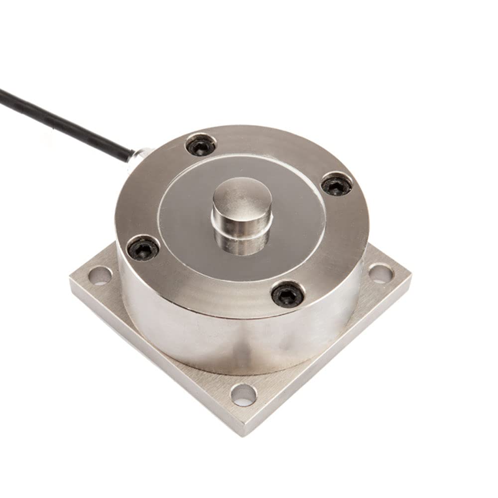
Image 8.1: Detailed dimension diagram of the ATO Compression Load Cell, showing various measurements in millimeters.
| Capacity | L1 (mm) | L2 (mm) | ΦC (mm) | ΦD (mm) | H (mm) | E (mm) | SR (mm) |
|---|---|---|---|---|---|---|---|
| 300~1000kg | 74 | 62 | 16 | 6.5 | 41 | 33 | 52 |
| 2ton | 90 | 73 | 20 | 8.5 | 53.5 | 44 | 70 |
9. Support and Warranty
ATO is committed to providing high-quality products and customer satisfaction. If you have any questions or encounter an issue with your ATO Compression Load Cell, please do not hesitate to contact us.
- Customer Support: Our engineering team offers one-on-one support to help you select the best sensor for your needs and resolve any product-related inquiries. We aim to respond within 12 hours.
- Warranty: For specific warranty terms and conditions, please refer to the product packaging or contact ATO customer service directly.
For more information and additional products, visit the ATO Store.


