1. Introduction
This manual provides comprehensive instructions for the installation, setup, and operation of the Aubric 12V Wireless RF Remote Control Switch. This kit includes a 4-channel relay module and two 433Mhz remote controls, designed for versatile wireless control of various electrical devices such as lights, ceiling fans, garage door openers, and more.
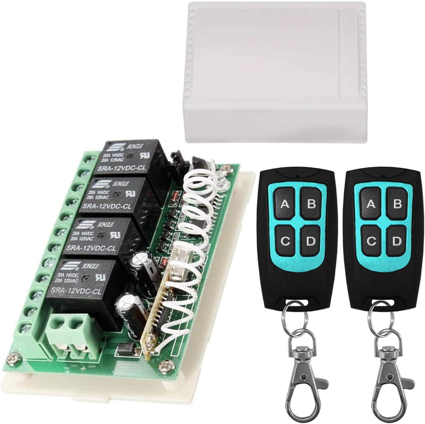
Figure 1.1: The Aubric 12V Wireless RF Remote Control Switch kit, including the 4-channel relay module, its protective casing, and two remote controls.
2. Safety Information
Please read and understand all safety warnings and instructions before installing or operating this product. Failure to do so may result in electric shock, fire, or serious injury.
- Always disconnect power before performing any wiring or maintenance.
- Ensure all wiring is done by a qualified electrician or in accordance with local electrical codes.
- Do not exceed the maximum current and voltage ratings specified for the relay module.
- Keep the device away from water, moisture, and extreme temperatures.
- This product is designed for low-voltage DC applications (12V). Do not connect to AC mains voltage directly.
3. Product Components
The Aubric 12V Wireless RF Remote Control Switch kit typically includes the following components:
- 4-Channel Relay Module: The main receiver unit with screw terminals for wiring.
- Protective Casing: A plastic enclosure for the relay module.
- Remote Controls (x2): Handheld 4-button transmitters (A, B, C, D).

Figure 3.1: Detailed view of the relay module, highlighting key components such as the learning button, indicator LED, antenna, 3-way jumper, power supply terminals, and relay output terminals (NC, C, NO).
4. Specifications
| Feature | Specification |
|---|---|
| Brand | Aubric |
| Model Number | BY06 |
| Power Source | DC 12V |
| Coil Voltage | 12 Volts |
| Current Rating (Each Relay) | 20 Amps (Max) |
| Wattage | 240 watts |
| RF Frequency | 433Mhz |
| Remote Control Range | Up to 164ft/50m (open area) |
| Contact Type | Normally Open (NO) |
| Contact Material | Silver |
| Connector Type | Screw Terminals |
| Mounting Type | Surface Mount |
| Product Dimensions | 2.05 x 0.98 x 2.95 inches |
| Item Weight | 3.99 ounces |
| Remote Battery Type | CR2016 Lithium Metal (included) |
5. Setup Guide
5.1. Unboxing and Initial Inspection
Carefully remove the relay module from its packaging. Open the protective casing to access the wiring terminals and the jumper cap for mode selection.

Figure 5.1: The relay module removed from its casing, showing the internal components and the open cover box.
5.2. Wiring Instructions
Connect the 12V DC power supply to the '+' and '-' terminals on the relay module. Each of the four relays has three terminals: NC (Normally Closed), C (Common), and NO (Normally Open). Connect your devices to the appropriate terminals based on your application. For most switching applications, you will connect your load to the NO and C terminals.

Figure 5.2: Example wiring diagram for controlling four lights using the relay module. The 12V DC power supply connects to the module, and each light is wired to the Common (C) and Normally Open (NO) terminals of a relay.

Figure 5.3: Example wiring diagram for controlling two DC motors using the relay module. Each motor is wired across two relays to allow for polarity reversal (forward/reverse control).
5.3. Setting Operating Modes
The relay module supports three different working modes, configured by adjusting the position of the 3-way jumper cap on the board. Ensure power is disconnected before changing jumper settings.

Figure 5.4: Jumper cap positions for different operating modes.
- Momentary Mode (Non Lock):
- Jumper Setting: The jumper does not connect any two pins (removed or placed on only one pin).
- Operation: Press and hold a button on the remote to turn the relay ON. Release the button to turn the relay OFF.
- Toggle Mode (Self-lock):
- Jumper Setting: The jumper connects pin 2 and pin 3.
- Operation: Press a button on the remote once to turn the relay ON. Press the same button again to turn the relay OFF.
- Latched Mode (Interlock):
- Jumper Setting: The jumper connects pin 1 and pin 2.
- Operation: Press one button to turn its corresponding relay ON and simultaneously turn OFF any other previously ON relays. This mode is typically used for applications where only one output should be active at a time (e.g., forward/reverse motor control).
5.4. Pairing Remote Controls
To pair a remote control with the receiver module:
- Ensure the relay module is powered on.
- Press the Learning Button on the relay module once. The LED indicator will turn off, indicating it's in learning mode.
- Within a few seconds, press any button (A, B, C, or D) on the remote control you wish to pair.
- The LED indicator on the module will flash three times and then turn on again, confirming successful pairing.
- Repeat for additional remote controls if desired.
5.5. Removing Paired Remotes (Clearing Codes)
To clear all paired remote controls from the receiver module:
- Press and hold the Learning Button on the relay module for approximately 6 seconds.
- The LED indicator will light up, then turn off, and then light up again, indicating that all previously learned codes have been successfully removed.
6. Operation
Once the relay module is wired and the remote controls are paired, operation is straightforward:
- Depending on the selected operating mode (Momentary, Toggle, or Latched), press the corresponding button (A, B, C, or D) on the remote control to activate or deactivate the connected device.
- The remote controls transmit a strong 433Mhz signal, allowing control through walls, floors, and doors within the specified range.
7. Wide Applications
The Aubric 12V Wireless RF Remote Control Switch is highly versatile and can be used in a variety of applications, including but not limited to:
- Garage Door Openers
- Outdoor Lighting
- Camper Modifications
- Water Pumps
- Electric Generators
- Motor-driven Curtains and Roller Blinds
- Car and Vehicle Modifications (e.g., auxiliary lights, winches)
- Anti-theft Alarm Control Panels
- Electric Door Release Locks

Figure 7.1: Visual representation of common applications for the wireless remote control switch, including garage door openers, camper modifications, outdoor lights, water pumps, and electric generators.
8. Maintenance
The Aubric 12V Wireless RF Remote Control Switch requires minimal maintenance. Follow these guidelines to ensure longevity:
- Keep the module and remotes clean and free from dust and debris. Use a soft, dry cloth for cleaning.
- Avoid exposing the devices to extreme temperatures, direct sunlight, or high humidity.
- If the remote control range decreases significantly, consider replacing the CR2016 battery inside the remote.
- Periodically check wiring connections to ensure they are secure.
9. Troubleshooting
| Problem | Possible Cause | Solution |
|---|---|---|
| Remote control not working | Low battery in remote; Remote not paired; Out of range; Obstruction | Replace remote battery; Re-pair remote (Section 5.4); Move closer to receiver; Remove obstructions. |
| Relay not activating/deactivating | Incorrect wiring; Overload; Faulty relay module | Check wiring connections (Section 5.2); Ensure load does not exceed 20A; Contact support if module is faulty. |
| Unexpected activation/deactivation | Interference; Power fluctuation; Faulty remote/module | Ensure module is away from strong RF sources; Consider adding a power conditioner; Clear all paired remotes and re-pair only necessary ones (Section 5.5); Contact support. |
| Short remote range | Low battery; Environmental interference; Physical obstructions | Replace remote battery; Minimize interference from other wireless devices; Ensure clear line of sight if possible. |
10. Warranty and Support
For technical support, troubleshooting assistance, or warranty inquiries, please contact Aubric customer service through the retailer where the product was purchased or visit the official Aubric website for contact information.
Please have your model number (BY06) and purchase details ready when contacting support.


