1. Introduction
This manual provides comprehensive instructions for the installation, operation, and maintenance of the Bennett Trim Tabs OBI9000-E One Box Indication Unit. This unit is designed to provide integrated helm control and indication for electric trim tab systems, offering a user-friendly interface without the need for an external control unit. Its compact design integrates the control unit's functionality directly into the keypad, simplifying installation and saving space at the helm.
The OBI9000-E is engineered to help reduce bow rise, achieve plane faster, and correct listing, enhancing the performance and comfort of your vessel.
2. Safety Information
Please read and understand all safety warnings and instructions before installing or operating this product. Failure to do so may result in product damage, property damage, or serious injury.
- Always disconnect power to the trim tab system before performing any installation, maintenance, or troubleshooting.
- Ensure all electrical connections are secure and properly insulated to prevent short circuits and corrosion.
- Do not operate the trim tabs if anyone is in the water near the transom.
- Verify trim tab position before and during operation to avoid unexpected vessel behavior.
- Consult a qualified marine technician if you are unsure about any installation or wiring procedures.
- Keep the control unit clean and dry. Avoid exposing it to excessive moisture or direct sunlight for prolonged periods.
3. Product Overview
The Bennett OBI9000-E is a compact and integrated helm control unit designed for ease of use and installation. It combines the control buttons and position indicators into a single, attractive keypad.
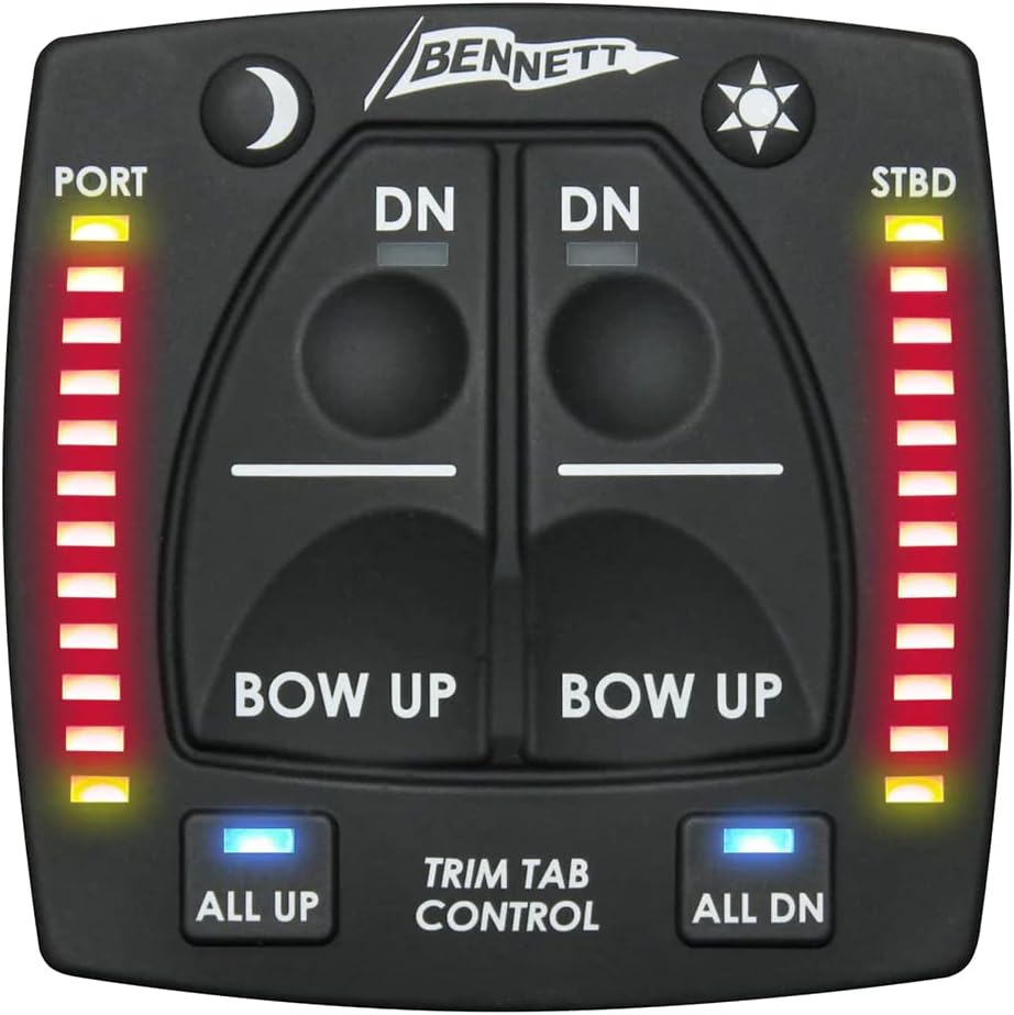
Figure 3.1: Front view of the Bennett OBI9000-E Trim Tab Control Unit. This image shows the main control panel with "DN" and "BOW UP" buttons for port and starboard tabs, "ALL UP" and "ALL DN" buttons, and LED indicators for tab position on both sides. It also features a moon icon for dimming and a sun icon for brightening the display.

Figure 3.2: Angled view of the Bennett OBI9000-E Trim Tab Control Unit, showcasing its compact design and the threaded mounting base. This perspective highlights the unit's low profile and how it integrates into the helm.
Key Features:
- Integrated Helm Control: All control functions are built directly into the keypad, eliminating the need for a separate control unit.
- Intuitive Buttons: Features dedicated "All Up" and "All Down" buttons for quick and easy full retraction or deployment of both tabs.
- LED Position Indicators: Bright LED lights on both the port and starboard sides clearly display the current position of your trim tabs at all times.
- Auto Tab Retraction: Tabs automatically retract to the full up position when the vessel's ignition is powered off, protecting them from damage.
- Easy Installation: Designed with a single lock nut for straightforward mounting.
- Compatibility: Can be used with various trim tab system brands.
4. Setup and Installation
Proper installation is crucial for the optimal performance and longevity of your OBI9000-E unit. Follow these steps carefully.

Figure 4.1: Installation diagram illustrating the required helm cut-out dimensions and the mounting process for the Bennett OBI9000-E. The diagram shows a 2.13" diameter cut-out hole and a 2.55" depth requirement, with the unit secured by a large threaded nut from below the helm surface. Wiring connections are also depicted.
Installation Steps:
- Choose Mounting Location: Select a flat, secure location on your helm that is easily accessible and visible to the operator. Ensure there is sufficient clearance behind the mounting surface for the unit's depth and wiring.
- Prepare Cut-Out: Using a suitable hole saw, create a circular cut-out in the helm panel. Refer to Figure 4.1 for precise dimensions: a 2.13 inch (approx. 54mm) diameter hole is required.
- Check Depth Clearance: Ensure there is at least 2.55 inches (approx. 65mm) of clear depth behind the helm panel for the unit to fit properly.
- Insert Unit: Carefully insert the OBI9000-E control unit into the prepared cut-out from the front of the helm.
- Secure with Lock Nut: From behind the helm panel, thread the large plastic lock nut onto the back of the control unit and tighten it securely by hand. Do not overtighten.
- Wire Connections: Connect the wiring harness from the OBI9000-E unit to your trim tab system's control module or actuators according to the wiring diagram provided with your specific trim tab system. The OBI9000-E typically uses standard marine electrical connectors. Ensure all connections are watertight and secure.
- Test Functionality: Once all connections are made, apply power to the trim tab system and test the functionality of the OBI9000-E unit. Verify that the tabs move correctly in response to button presses and that the LED indicators accurately reflect their position.
Note: This unit is designed for electric trim tab systems. If you have a hydraulic system, ensure compatibility or consult your system's manual.
5. Operating Instructions
The OBI9000-E provides intuitive control over your vessel's trim tabs. Familiarize yourself with the controls before operating your vessel.
Control Functions:
- "DN" Buttons (Port/Starboard): Press the "DN" button on the respective side (Port or Starboard) to deploy that trim tab downwards. This will lower the bow on that side of the vessel.
- "BOW UP" Buttons (Port/Starboard): Press the "BOW UP" button on the respective side (Port or Starboard) to retract that trim tab upwards. This will raise the bow on that side of the vessel.
- "ALL UP" Button: Press this button to simultaneously retract both port and starboard trim tabs to their full "up" position. This is useful for high-speed operation or when docking.
- "ALL DN" Button: Press this button to simultaneously deploy both port and starboard trim tabs to their full "down" position. This can assist in getting on plane faster.
- LED Position Indicators: The vertical rows of LEDs on the "PORT" and "STBD" sides indicate the current position of each trim tab. More illuminated LEDs mean the tab is further deployed (down).
- Brightness Control:
- Moon Icon Button: Press this button to dim the LED indicators and button backlighting for night operation.
- Sun Icon Button: Press this button to brighten the LED indicators and button backlighting for daytime visibility.
General Operation Tips:
- Make small, incremental adjustments to the trim tabs.
- Observe the vessel's attitude and performance after each adjustment.
- Use trim tabs to correct listing (side-to-side imbalance) by deploying the tab on the higher side of the vessel.
- For optimal planing, deploy both tabs slightly until the bow lowers and the vessel achieves a comfortable running angle.
- Retract tabs fully when operating at high speeds or in rough seas, unless specific trim is required.
6. Maintenance
The OBI9000-E unit is designed for durability in the marine environment. Regular, simple maintenance will ensure its continued reliable operation.
- Cleaning: Periodically wipe the control panel with a soft, damp cloth to remove salt residue, dirt, and grime. Do not use abrasive cleaners or solvents.
- Inspection: Regularly inspect the unit for any signs of physical damage, loose connections, or corrosion. Address any issues promptly.
- Wiring: Check wiring connections behind the helm for tightness and signs of corrosion. Apply marine-grade dielectric grease to connections if necessary to prevent corrosion.
- Environmental Protection: While designed for marine use, protecting the unit from prolonged direct exposure to harsh UV rays when not in use (e.g., with a helm cover) can extend its lifespan.
7. Troubleshooting
If you experience issues with your OBI9000-E unit, refer to the following common problems and solutions. For more complex issues, contact Bennett Marine support or a qualified marine technician.
| Problem | Possible Cause | Solution |
|---|---|---|
| Unit has no power / LEDs are off. | No power to the unit; Blown fuse; Loose wiring connection. | Check vessel's power supply to the trim tab system. Inspect the fuse in the trim tab system's circuit. Verify all wiring connections are secure. |
| Trim tabs do not respond to button presses. | No power to actuators; Faulty wiring; Actuator issue; System lockout. | Ensure the unit has power (LEDs are on). Check wiring from the OBI9000-E to the trim tab actuators/controller. Consult your trim tab system's manual for actuator troubleshooting. Some systems have safety lockouts; ensure ignition is on. |
| LED indicators are inaccurate or erratic. | Sensor issue; Wiring issue; Calibration needed. | Check connections to the trim tab position sensors. Refer to your trim tab system's manual for sensor troubleshooting or calibration procedures. |
| "ALL UP" or "ALL DN" buttons do not work. | Specific button malfunction; System communication issue. | Test individual tab controls. If individual controls work, the issue might be with the "ALL" command signal or the unit itself. Contact support. |
8. Specifications
| Feature | Detail |
|---|---|
| Model Number | 6BT-50103-41-00 |
| Brand | Bennett Marine |
| Item Package Dimensions (L x W x H) | 11 x 11 x 4 inches |
| Package Weight | 1.25 Pounds |
| Item Weight | 2 Pounds |
| Required Helm Cut-Out Diameter | 2.13 inches (approx. 54mm) |
| Required Helm Depth Clearance | 2.55 inches (approx. 65mm) |
| Compatibility | Electric Trim Tab Systems (also compatible with other trim tab system brands) |
| Date First Available | June 29, 2020 |
9. Warranty and Support
For specific warranty information regarding your Bennett Trim Tabs OBI9000-E One Box Indication Unit, please refer to the warranty card included with your product or visit the official Bennett Marine website. Warranty terms and conditions may vary.
For technical support, troubleshooting assistance beyond this manual, or to inquire about replacement parts, please contact Bennett Marine customer service directly. Contact information can typically be found on their official website or product packaging.
It is recommended to keep your purchase receipt as proof of purchase for warranty claims.


