1. Introduction
This manual provides essential information for the safe and effective operation of your INGCO 1000A Digital AC/DC Clamp Meter, Model Dm2002. Please read this manual thoroughly before use and retain it for future reference. This device is designed for measuring AC/DC current, AC/DC voltage, resistance, capacitance, continuity, frequency, temperature, inrush current, VFD, LOZ, and NCV.

Figure 1: INGCO 1000A Digital AC/DC Clamp Meter showing its measurement capabilities for 1000A AC current, 750V AC voltage, 1000V DC voltage, and 60MΩ resistance.
2. Safety Information
Always adhere to safety precautions when using electrical testing equipment. Failure to do so may result in injury or damage to the meter.
- Do not exceed the maximum input values specified for each measurement range.
- Ensure the test leads are in good condition and properly connected before making measurements.
- Do not use the meter if it appears damaged or if the battery cover is not properly closed.
- Always disconnect the test leads from the circuit before changing functions.
- Be cautious when working with voltages above 30V AC RMS, 42V peak, or 60V DC, as they pose a shock hazard.
- Use appropriate personal protective equipment (PPE), such as safety glasses and insulated gloves.
- Do not operate the meter in explosive gas, vapor, or dusty environments.
3. Product Overview
Familiarize yourself with the components of your clamp meter.
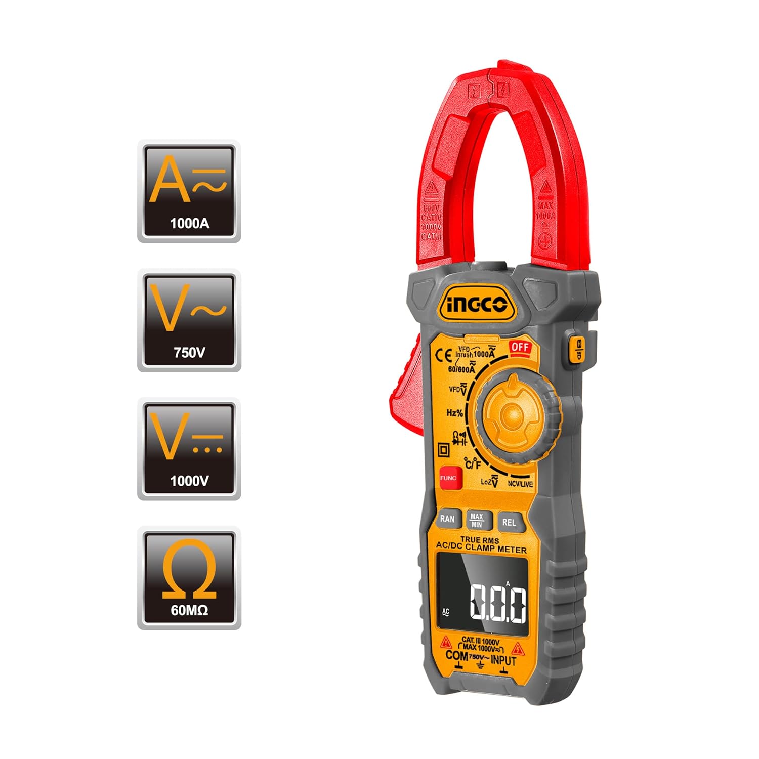
Figure 2: Front view of the INGCO Clamp Meter, highlighting the clamp jaw, function dial, LCD display, and input terminals.
Key Components:
- Clamp Jaw: Used for non-contact AC/DC current measurement.
- Function Dial: Selects the desired measurement mode.
- LCD Display: Shows measurement readings, units, and indicators.
- Input Terminals: For connecting test leads (COM, VΩHzCAPTemp).
- Buttons: FUNC (Function), RAN (Range), MAX/MIN, REL (Relative), ZERO, HOLD, Backlight/Flashlight.

Figure 3: Detailed view of the function dial, showing various measurement modes including VFD, Hz%, °C/°F, LoZ, and NCV/LIVE.

Figure 4: Close-up of the control buttons, including RAN, MAX/MIN, REL/ZERO, and FUNC, used for advanced measurement options.
4. Setup
4.1 Battery Installation
- Ensure the meter is powered off.
- Locate the battery compartment on the back of the meter.
- Use a screwdriver to open the battery cover.
- Insert the required batteries (typically AAA, refer to the compartment label) observing correct polarity.
- Replace the battery cover and secure it with the screw.

Figure 5: Multi-view image showing the back of the clamp meter with the battery compartment open, indicating where batteries are inserted.
4.2 Connecting Test Leads
For voltage, resistance, capacitance, continuity, frequency, and temperature measurements, connect the test leads:
- Insert the black test lead into the COM (common) input terminal.
- Insert the red test lead into the VΩHzCAPTemp input terminal.
5. Operating Instructions
5.1 Power On/Off
Turn the function dial from the OFF position to any desired measurement function to power on the meter. To power off, turn the dial back to the OFF position.
5.2 Auto Power Off
The meter features an automatic power-off function. If no operation is performed for approximately 15 minutes, the meter will automatically shut down to conserve battery life. Press any button or turn the function dial to reactivate it.

Figure 6: Visual representation of the 15-minute auto power-off feature, designed to save battery life.
5.3 AC/DC Current Measurement (Clamp Function)
- Turn the function dial to the A~ (AC Current) or A= (DC Current) position.
- Press the clamp trigger to open the clamp jaw.
- Enclose only one conductor with the clamp jaw. Ensure the jaw is fully closed.
- Read the current value on the LCD display.
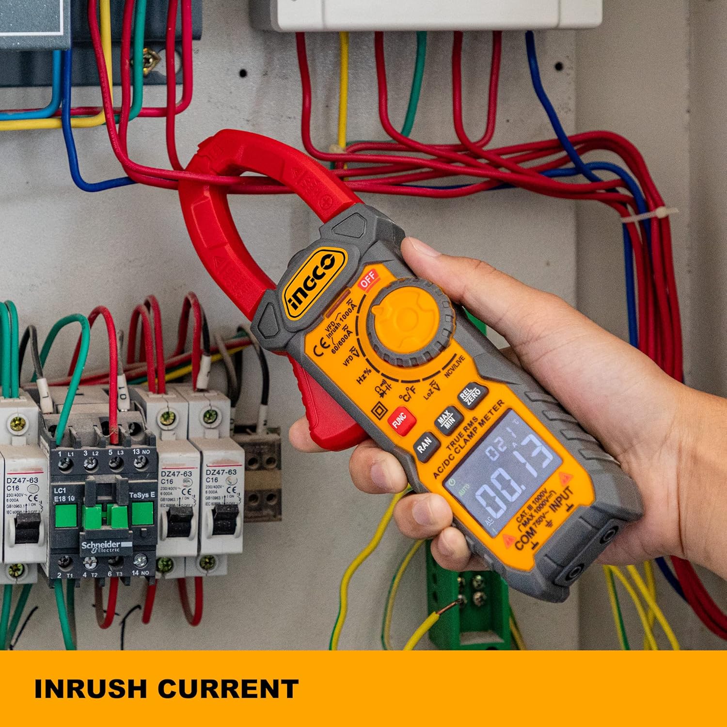
Figure 7: The clamp meter being used to measure inrush current within an electrical panel, demonstrating its non-contact current measurement capability.
5.4 AC/DC Voltage Measurement
- Connect the test leads as described in Section 4.2.
- Turn the function dial to the V~ (AC Voltage) or V= (DC Voltage) position.
- Connect the test probes in parallel to the circuit or component under test.
- Read the voltage value on the LCD display.

Figure 8: The clamp meter's test leads connected to a power strip, illustrating its use for accurate True-RMS voltage measurements.
5.5 Resistance, Capacitance, Continuity, Frequency, Temperature Measurement
- Connect the test leads as described in Section 4.2.
- Turn the function dial to the appropriate position (Ω for Resistance, ∔ for Capacitance, for Continuity, Hz% for Frequency, °C/°F for Temperature).
- If multiple functions share a dial position, press the FUNC button to cycle through them.
- Connect the test probes to the component under test.
- Read the value on the LCD display. For continuity, a buzzer sounds if resistance is less than 30Ω.
5.6 Inrush Current Measurement
This function captures the peak current when a device is first powered on. It takes approximately 100ms to capture the inrush current.
- Turn the function dial to the A~ position.
- Press the INRUSH button (if available, or refer to specific model instructions for activation).
- Clamp the jaw around the single conductor of the device to be tested.
- Power on the device and observe the inrush current reading.
5.7 VFD (Variable Frequency Drive) Measurement
This mode is designed for accurate voltage and frequency measurements on variable frequency drives.
- Turn the function dial to the VFD position.
- Connect the test leads to the circuit.
- Read the voltage and frequency values on the display.
5.8 LOZ (Low Impedance) Measurement
The LOZ function provides a low input impedance mode to eliminate ghost voltages, ensuring more accurate readings in certain circuits.
- Turn the function dial to the LoZ position.
- Connect the test leads to the circuit.
- Read the voltage value on the display.
5.9 NCV (Non-Contact Voltage) Detection
This feature allows for quick detection of AC voltage without direct contact.
- Turn the function dial to the NCV/LIVE position.
- Move the top end of the meter near the conductor or outlet.
- The meter will beep and/or an LED will flash if AC voltage is detected.
5.10 Data Hold Function
Press the HOLD button to freeze the current reading on the display. Press it again to release the hold function.

Figure 9: The clamp meter's display showing a 'H' indicator, signifying that the data hold function is active, making readings easy to record.
5.11 Backlight and Flashlight
Press the backlight/flashlight button to illuminate the display for better visibility in low-light conditions. Press and hold the button to activate the flashlight function.
6. Maintenance
6.1 Cleaning
Wipe the meter with a damp cloth and mild detergent. Do not use abrasives or solvents. Ensure the meter is dry before use.
6.2 Battery Replacement
When the battery indicator appears on the display, replace the batteries as described in Section 4.1. Remove batteries if the meter will not be used for an extended period.
6.3 Storage
Store the meter in a cool, dry place, away from direct sunlight and extreme temperatures. Keep it in its protective case when not in use.
7. Troubleshooting
| Problem | Possible Cause | Solution |
|---|---|---|
| Meter does not power on. | Dead or incorrectly installed batteries. | Check battery polarity; replace batteries. |
| No reading or unstable reading. | Incorrect function selected; poor test lead connection; out of range. | Select correct function; ensure leads are firmly connected; check if measurement is within meter's range. |
| Continuity buzzer not sounding. | Resistance is too high; continuity function not selected. | Ensure resistance is below 30Ω; select continuity mode. |
| Inaccurate current reading. | Multiple conductors in clamp jaw; jaw not fully closed. | Ensure only one conductor is clamped; close jaw completely. |
8. Specifications
| Feature | Specification |
|---|---|
| Model Number | Dm2002 |
| AC Current Range | Up to 1000A |
| DC Current Range | Up to 1000A |
| AC Voltage Range | Up to 750V |
| DC Voltage Range | Up to 1000V |
| Resistance Range | Up to 60MΩ |
| Display Counts | 6000 Counts |
| True RMS | Yes |
| Inrush Current Capture | 100ms |
| Auto Power Off | Approx. 15 minutes |
| Continuity Buzzer | < 30Ω |
| Product Dimensions | 9.84 x 3.35 x 8.66 inches |
| Item Weight | 750 Grams (1.65 Pounds) |
| Power Source | Battery Powered |
| Manufacturer | Ingco |
9. Warranty and Support
INGCO offers a 90-day refund or replacement policy for this clamp multimeter if you are not 100% satisfied. For any issues or support inquiries, please contact INGCO customer service via email. They aim to resolve concerns within 24 hours.
For further assistance, please visit the official Ingco store: Ingco Store on Amazon


