1. Introduction
This manual provides essential information for the installation, operation, and maintenance of the Sepam Series 80 S80 Electrical Network Protection Unit, specifically models 59704 and SEP383. This device is designed to provide advanced protection and control for electrical networks, ensuring reliability and safety. Please read this manual thoroughly before attempting any installation or operation.
The Sepam Series 80 S80 unit is a sophisticated device for comprehensive relay protection, featuring an HMI (Human Machine Interface) for local control and monitoring, and supporting various communication options including TCP/IP and Logipam.
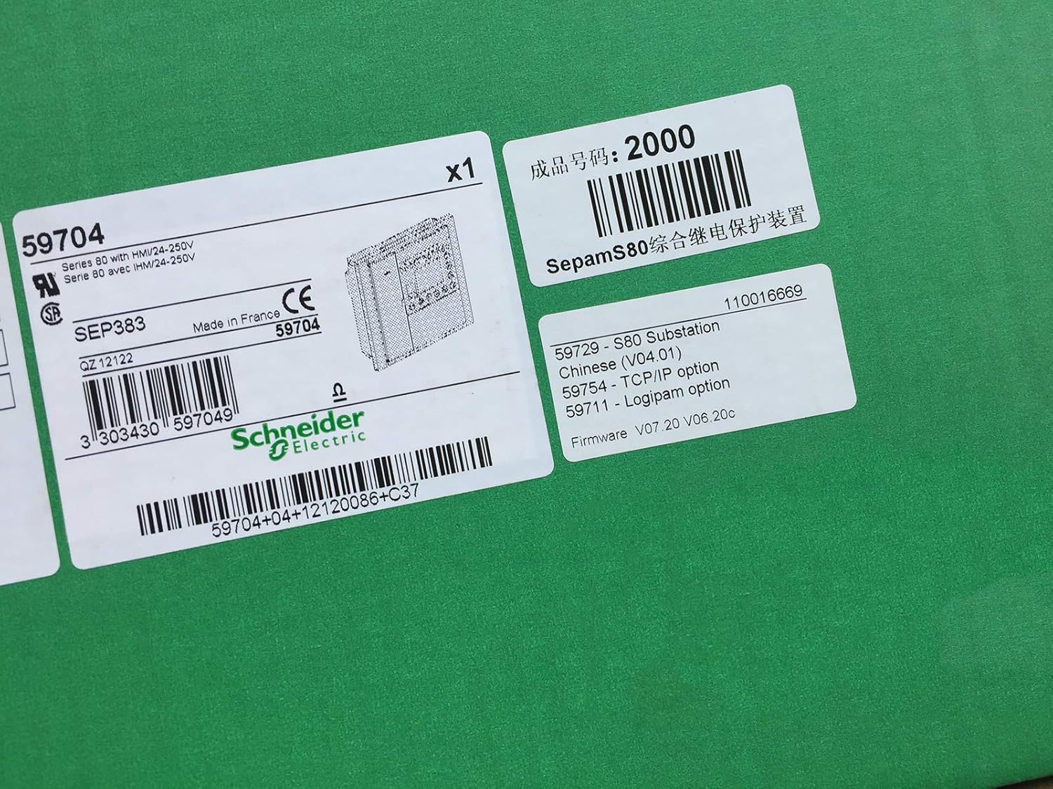
Figure 1: Sepam Series 80 S80 Product Label. This image displays the product label for the Sepam Series 80 S80 unit, showing key identifiers such as model number 59704, SEP383, "Made in France", CE marking, and Schneider Electric branding. It also indicates "Series 80 with HMI/24-250V" and various option codes like 59729 (S80 Substation), 59754 (TCP/IP option), and 59711 (Logipam option), along with firmware versions V07.20 and V06.20c.
2. Safety Information
Always observe the following safety precautions to prevent injury and damage to the equipment:
- Installation and maintenance should only be performed by qualified personnel.
- Ensure the power supply is disconnected before performing any work on the unit.
- Use appropriate personal protective equipment (PPE) such as insulated gloves and safety glasses.
- Verify all wiring connections are secure and correct before applying power.
- Do not operate the unit if it appears damaged.
- Adhere to all local and national electrical codes and regulations.
3. Setup
3.1 Unpacking
Carefully unpack the Sepam Series 80 S80 unit and inspect it for any signs of damage during transit. Retain all packaging materials for future transport or storage.
3.2 Mounting
The unit is designed for panel mounting. Ensure the mounting surface is stable and provides adequate ventilation. Refer to the specific mounting dimensions provided in the product documentation for precise installation.
3.3 Wiring
Connect the power supply (24-250V), current transformers (CTs), voltage transformers (VTs), and control circuits according to the wiring diagrams specific to your application. Pay close attention to polarity and phase sequencing. All connections must be tight and secure to prevent loose contacts and potential hazards.
- Power Supply: Connect the 24-250V AC/DC auxiliary power.
- Current Inputs: Connect CT secondary circuits to the designated terminals.
- Voltage Inputs: Connect VT secondary circuits to the designated terminals.
- Digital Inputs/Outputs: Connect control and signaling circuits as required.
- Communication Ports: Connect Ethernet cables for TCP/IP communication or other cables for Logipam as per system design.
4. Operating Instructions
4.1 Powering On
Once all connections are verified, apply auxiliary power to the unit. The HMI display will illuminate, and the unit will perform a self-test. Wait for the unit to complete its startup sequence before proceeding.
4.2 HMI Navigation
The Human Machine Interface (HMI) allows for local configuration, monitoring, and control. Use the navigation buttons (up, down, left, right, enter) to browse through menus, view measurements, check event logs, and adjust settings. Consult the detailed HMI guide for specific menu structures and parameter definitions.
4.3 Basic Operation
After startup, the unit will begin monitoring the electrical network. Protection functions will be active based on the configured settings. You can view real-time measurements (currents, voltages, power, frequency) and status indicators on the HMI. Event logs record all significant occurrences, including trips and alarms.
5. Maintenance
Regular maintenance ensures the longevity and reliable operation of your Sepam Series 80 S80 unit.
5.1 Routine Checks
- Periodically inspect the unit for any visible damage, loose connections, or signs of overheating.
- Ensure ventilation openings are clear of dust and debris.
- Check the HMI display for any error messages or abnormal indications.
- Verify that all protection functions are active and correctly configured.
5.2 Cleaning
Clean the exterior of the unit with a soft, dry cloth. Do not use abrasive cleaners or solvents. Ensure no moisture enters the unit.
5.3 Firmware Updates
Firmware updates (e.g., V07.20, V06.20c) may be released to improve performance, add features, or address issues. Consult Schneider Electric's official support channels for information on available updates and the procedure for installation. Firmware updates should only be performed by qualified personnel.
6. Troubleshooting
This section provides guidance for common issues. For complex problems, contact technical support.
| Problem | Possible Cause | Solution |
|---|---|---|
| Unit does not power on. | No auxiliary power; incorrect wiring; internal fault. | Check power supply connections and voltage. Verify wiring. If problem persists, contact support. |
| HMI display is blank or frozen. | Software issue; hardware malfunction. | Attempt a power cycle. If issue continues, contact technical support. |
| Protection functions not active. | Incorrect configuration; sensor wiring issue. | Verify configuration settings. Check CT/VT connections. |
| Unexpected trips or alarms. | Network disturbance; incorrect settings; faulty sensor. | Review event logs for details. Check network conditions. Verify protection settings. |
7. Specifications
Key technical specifications for the Sepam Series 80 S80 unit:
- Model: S80 59704 SEP383
- Brand: Schneider Electric
- Auxiliary Power Supply: 24-250V AC/DC
- Phase Type: Three Phase
- Material: Metal enclosure
- Firmware Versions: V07.20, V06.20c (as per product label)
- Communication Options: TCP/IP (59754), Logipam (59711)
- Product Number (from label): 2000
- Barcode (from label): 3303430597049
- ASIN: B08BLGNP5B
- UPC: 782950736795
8. Warranty & Support
For warranty information, please refer to the terms and conditions provided at the time of purchase or contact your authorized Schneider Electric distributor. Technical support is available for assistance with installation, configuration, and troubleshooting.
For support, please visit the official Schneider Electric website or contact their customer service department. When contacting support, please have your product model (S80 59704 SEP383) and serial number ready.