
KEYESTUDIO KEYESTUDIO Robot Arm Starter Kit
KEYESTUDIO 4DOF Robot Arm Starter Kit for Arduino
Instruction Manual
1. Introduction
This manual provides detailed instructions for the assembly, setup, and operation of the KEYESTUDIO 4DOF Robot Arm Starter Kit for Arduino. This kit is designed for individuals aged 15 and above with a foundational understanding of electronic programming, offering a practical platform to explore robotics and coding principles.
The kit includes a 4-Degrees-of-Freedom (4DOF) robotic arm, control boards, servos, and various components necessary for construction. It supports multiple control methods, including a wired joystick, Bluetooth application for Android/iOS devices, and compatibility with a PS2 wireless controller (controller not included).
2. Package Contents
Please verify all components are present upon opening the package. Refer to the image below for a visual representation of the included parts.

Figure 2.1: Complete list of components included in the kit.
- Robotic Arm (pre-assembled sections) x1
- Main Control Board x1
- Motor/Servo Drive Shield with PS2 Interface x1
- Joystick Modules x2
- 180-degree MG90S (14g) Black Servos x4
- HM-10 BT-4.0 Module x1
- AM/BM USB Cable x1
- Battery Holder (for 18650 batteries, batteries not included) x1
- Acrylic Boards (for base and joystick) x3
- 3*40MM Black-yellow Cross Screwdriver x1
- Male to Female Dupont Wires x25
- Female to Female Dupont Wires x5
- 12CM Winding Pipe x1
- 3*100MM Black Cable Ties x10
- Galvanized M2+M3 Double end Wrench x1
- M3*6MM Round Head Screws x32
- M2*8MM Round Head Screws x3
- M3*10MM Round Head Screws x3
- M3*45MM Dual-pass Hexagonal Copper Pillars x4
- M3*10MM Dual-pass Hexagonal Copper Pillars x14
- M3 Hex Nickel Plated Stainless Steel Nuts x3
- M2 Hex Nickel Plated Stainless Steel Nuts x3
3. Assembly Instructions
The robotic arm mechanism comes partially pre-assembled. This section focuses on completing the base, joystick, and integrating the main arm structure. For highly detailed, step-by-step visual instructions, it is recommended to visit the official KEYESTUDIO wiki for the '4DOF Robot Arm Kit V2.0 for Arduino'.
3.1 Base Assembly
- Identify the main base acrylic board.
- Attach the four M3*45MM dual-pass hexagonal copper pillars to the corners of the base board using M3 screws.
- Mount the Motor/Servo Drive Shield onto these pillars, securing it with M3 screws.
- Attach the main control board (Arduino compatible) to the designated area on the Motor/Servo Drive Shield.
3.2 Joystick Assembly
- Take the joystick acrylic board.
- Mount the two joystick modules onto the board using the provided screws and nuts.
- Connect the joystick modules to the main control board using the male-to-female Dupont wires as indicated in the wiring diagram (Section 3.3).
3.3 Wiring Connections
Careful wiring is crucial for proper functionality. Refer to the diagram below for connecting the servos, joystick, and power components to the Motor/Servo Drive Shield.
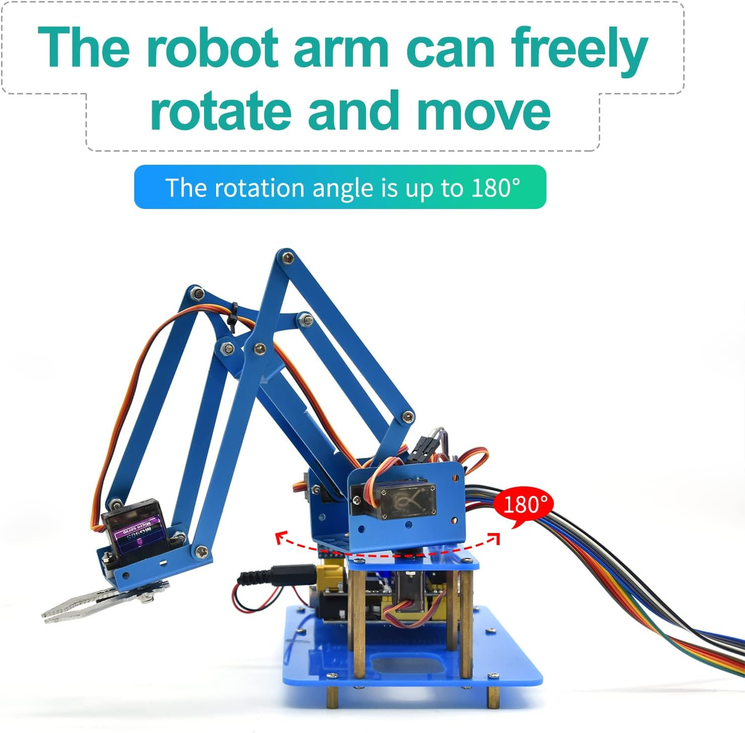
Figure 3.1: Servo Drive Expansion Board Parameters and Pinout.
- Servo Connections: Connect the 4 servos to the designated servo pins on the Motor/Servo Drive Shield. Ensure correct polarity (Signal, VCC, GND). The robotic arm typically uses 4 servos for its 4 degrees of freedom.
- Joystick Connections: Connect the joystick modules to the analog input pins (A0-A5) and digital pins (D8-D9) on the shield as per the provided code and diagram.
- Bluetooth Module (HM-10 BT-4.0): Connect the HM-10 module to the Bluetooth-compatible interface pins (V, G, RX, TX) on the shield.
- Power Supply: Connect the battery holder (with two 18650 batteries, not included) to the external power jack (DC 7-9V) or use a compatible AC adapter. Ensure the slide switch for external power is in the 'ON' position when using external power.
- USB Connection: Use the AM/BM USB cable to connect the main control board to your computer for programming.
Note: Some servo wires may require extensions (included in the kit) to reach their respective connection points on the shield.
4. Software Setup and Programming
To operate the robot arm, you will need to set up the Arduino Integrated Development Environment (IDE) and upload the provided sample code.
4.1 Arduino IDE Installation
- Download and install the latest version of the Arduino IDE from the official Arduino website (www.arduino.cc/en/software).
- Install necessary drivers for your specific Arduino-compatible board if prompted during installation or when connecting the board for the first time.
4.2 Library Installation
The robot arm code typically requires specific libraries, such as the Servo library. These can usually be installed via the Arduino IDE's Library Manager (Sketch > Include Library > Manage Libraries...). Search for and install any libraries specified in the kit's documentation or sample code.
4.3 Code Upload
- Obtain the sample code for the KEYESTUDIO 4DOF Robot Arm from the official KEYESTUDIO wiki or product support page.
- Open the downloaded code (.ino file) in the Arduino IDE.
- Select the correct board type (e.g., Arduino Uno) under Tools > Board.
- Select the correct serial port for your connected board under Tools > Port.
- Click the 'Upload' button (right arrow icon) to compile and upload the code to your robot arm's control board.
- Monitor the output window for any compilation or upload errors.
5. Operating Instructions
The KEYESTUDIO 4DOF Robot Arm supports multiple control methods:
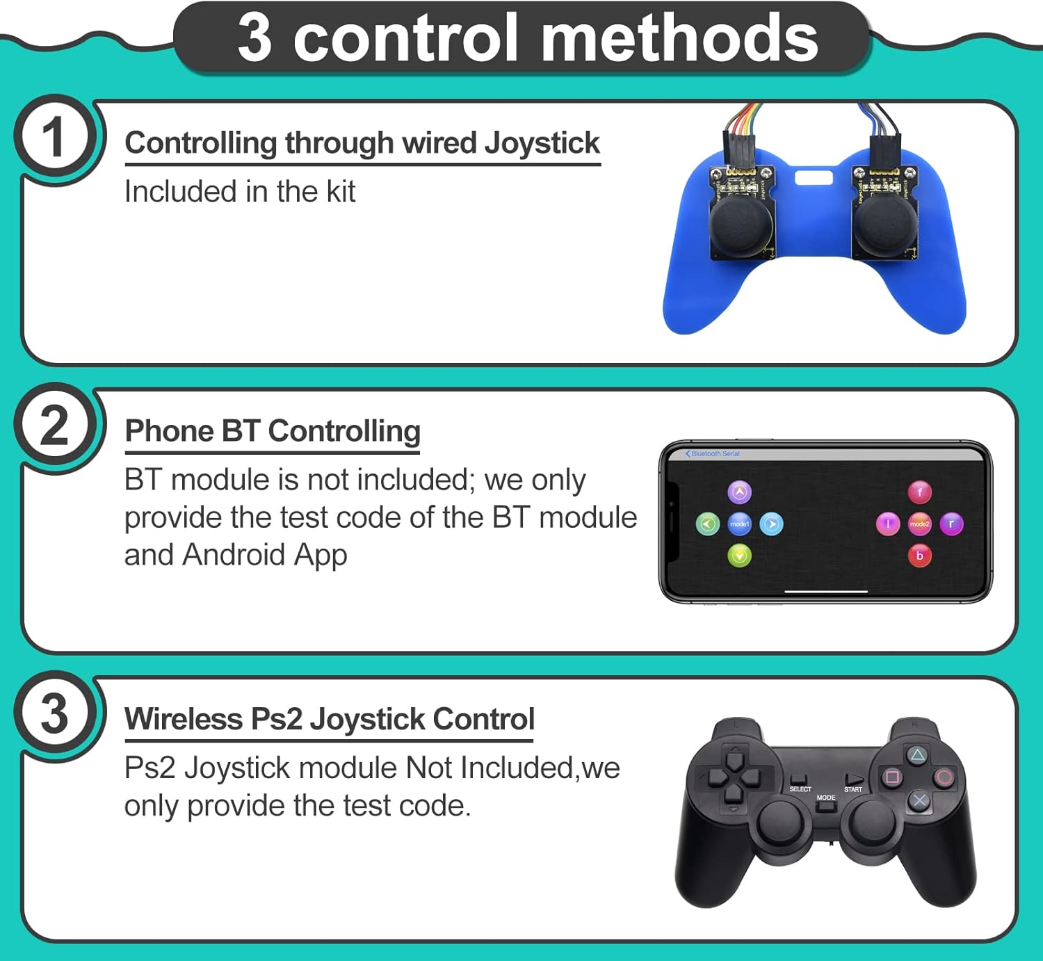
Figure 5.1: Overview of available control methods.
5.1 Wired Joystick Control
The kit includes two joystick modules that can be wired directly to the control board. Once the appropriate code is uploaded, manipulate the joysticks to control the movement of the robotic arm's various joints and the gripper.
5.2 Bluetooth App Control (Android/iOS)
The HM-10 BT-4.0 module allows for wireless control via a smartphone application. You will need to download the compatible KEYESTUDIO app (available for Android and iOS) and pair it with the HM-10 module. The app provides a graphical interface to send commands to the robot arm.
5.3 Wireless PS2 Joystick Control
While a PS2 wireless controller is not included in this kit, the Motor/Servo Drive Shield has a PS2 interface. Sample code and instructions for integrating a PS2 controller are typically provided on the KEYESTUDIO wiki, allowing for an alternative wireless control method if you acquire a compatible PS2 controller.
6. Maintenance
To ensure the longevity and optimal performance of your robot arm kit, follow these maintenance guidelines:
- Cleaning: Keep the acrylic parts and electronic components free from dust and debris. Use a soft, dry cloth for cleaning. Avoid using liquids directly on electronic parts.
- Joints and Servos: Periodically check the tightness of screws and nuts at the joints. Over time, vibrations can loosen them. Ensure servos operate smoothly without excessive force or binding.
- Wiring: Inspect all wire connections for secure fit. Loose connections can lead to intermittent operation or component damage. Use the winding pipe and cable ties to manage wires neatly and prevent snagging.
- Power Supply: If using 18650 batteries, ensure they are charged correctly and are not damaged. Always use a power supply within the recommended voltage range (DC 7-9V) to prevent damage to the control board and servos.
7. Troubleshooting
If you encounter issues with your robot arm, consider the following troubleshooting steps:
- Arm Not Moving:
- Check all power connections. Ensure the power supply is adequate and correctly connected.
- Verify servo connections are secure and correctly oriented (Signal, VCC, GND).
- Confirm the correct code has been uploaded to the Arduino board.
- Ensure the correct board and port are selected in the Arduino IDE before uploading.
- Erratic Movement:
- This often indicates insufficient power. Ensure your power supply can provide enough current (e.g., 2A or more for 7-9V).
- Check for loose wiring or interference.
- Verify servo angles in the code are within their operational limits (0-180 degrees) to prevent mechanical stress.
- Bluetooth Connection Issues:
- Ensure the HM-10 module is correctly wired and powered.
- Confirm the Bluetooth module is enabled on your smartphone and the app is correctly configured to connect.
- Check for other Bluetooth devices causing interference.
- Servos Getting Hot or Seizing:
- This can be due to excessive load or incorrect servo angle limits in the code, causing the servo to constantly try to move beyond its physical stop.
- Ensure the mechanical assembly allows free movement of the arm without binding.
- Consider replacing faulty servos if the issue persists after checking power and code.
8. Specifications
| Feature | Detail |
|---|---|
| Model Number | KEYESTUDIO Robot Arm Starter Kit |
| Degrees of Freedom (DOF) | 4 |
| Control Methods | Wired Joystick, Bluetooth App (Android/iOS), PS2 Joypad (code provided, controller not included) |
| Servos Included | 4 x 180-degree MG90S (14g) Black Servos |
| Recommended Age | 15+ years (with programming knowledge) |
| Power Supply (External) | DC 7-9V (e.g., 2x 18650 batteries or compatible AC adapter) |
| Weight | 1.36 pounds (approx.) |
| Package Dimensions | 11.61 x 7.95 x 3.03 inches (approx.) |
9. Support and Warranty
KEYESTUDIO is committed to providing technical support for its products. If you encounter any issues or have questions regarding the assembly, programming, or operation of your robot arm kit, please reach out to KEYESTUDIO customer support. You can typically find contact information on the product packaging or the official KEYESTUDIO website.
While specific warranty details are not provided in this manual, KEYESTUDIO generally offers support for product defects and operational assistance. Please retain your proof of purchase for any warranty claims.
Related documentsKEYESTUDIO Robot Arm Starter Kit


Ask a question about this manual
Ask about setup, troubleshooting, compatibility, parts, safety, or missing instructions. Manuals+ will review the question and use this page’s manual context to help answer it.