Introduction
The Treedix LCR-TC1 is a versatile multifunction component tester designed for hobbyists and professionals. It accurately identifies and measures various electronic components, including NPN and PNP transistors, N-channel and P-channel MOSFETs, diodes (including dual diodes), resistors, inductors, capacitors, and more. Featuring a 1.8-inch TFT graphic display, it provides clear and detailed test results. This manual provides essential information for safe and effective use of your LCR-TC1 tester.

Figure 1: Treedix LCR-TC1 Multifunction Component Tester
Safety Information
Please read and understand the following safety precautions before using the LCR-TC1 tester:
- The built-in lithium-ion battery must not be immersed in water or placed near heat sources. This can cause fire, explosion, or other hazards.
- Always discharge capacitors before connecting them to the tester. Failure to do so can damage the tester and pose a safety risk due to stored electrical energy.
- It is not recommended to use the tester to measure batteries. If you must measure a battery, ensure its voltage is less than 4.5V. Measuring batteries with higher voltage can damage the tester.
- Do not attempt to disassemble or modify the tester. Repairs should only be performed by qualified personnel.
- Keep the device away from dust, moisture, and extreme temperatures.
Package Contents
Verify that all items are present in your package:
- 1 x LCR-TC1 Graphical Tester
- 1 x Electronic Component Set (for testing)
- 3 x Test Hooks
- 1 x USB Cable (for charging/power)
- 1 x Japanese Manual (refer to this English manual for detailed instructions)
Specifications
| Feature | Specification |
|---|---|
| Display | 1.8-inch TFT Screen |
| Diode Range | <4.5V |
| Transistor Detection Area | 0.01V - 4.5V |
| Zener Diode Detection Area | 0.01V - 30V |
| Triac Range | IGT <6mA |
| Capacitance Measurement | 25pF - 100mF |
| Resistance Measurement | 0.01Ω - 50MΩ |
| Inductance Measurement | 0.01mH - 20H |
| Battery Voltage Measurement | 0.1V - 4.5V |
| Power Mode | Rechargeable Lithium Battery (internal) |
| Dimensions | Approx. 90 x 50 x 25mm |
Setup
Before first use, ensure the device is fully charged using the provided USB cable. The device features a built-in rechargeable lithium battery. Connect the USB cable to the device and a suitable USB power source (e.g., computer USB port, USB wall adapter).
The LCR-TC1 has a ZIF (Zero Insertion Force) socket for easy component insertion. Lift the lever to open the socket, insert the component leads into the appropriate pins (1, 2, or 3), and then press the lever down to secure the component.
Operating Instructions
The LCR-TC1 operates with a single button. Press the "Start" button to initiate a test. The device will automatically identify the component and display its parameters on the TFT screen.
General Testing Procedure:
- Ensure the component is discharged, especially capacitors.
- Lift the ZIF socket lever.
- Insert the component leads into pins 1, 2, and/or 3 of the ZIF socket. For 2-pin components, use any two pins (e.g., 1 and 2). For 3-pin components, use pins 1, 2, and 3.
- Press the ZIF socket lever down to secure the component.
- Press the "Start" button. The tester will perform the measurement and display the results.
- After the test, lift the lever and remove the component.
Component Specific Testing Examples:
Testing Transistors (NPN/PNP)
The tester automatically identifies NPN and PNP transistors and displays their pinout (Emitter, Base, Collector), current gain (hFE), and base-emitter voltage (Uf).
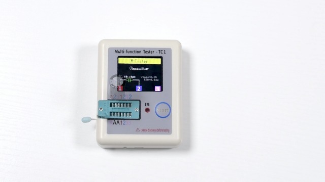
Figure 2: Testing an NPN Transistor. The display shows the component type (BJT-NPN), pin configuration (E, B, C), hFE, and Uf values.
Testing Inductors
Insert the inductor leads into the test socket. The tester will measure and display the inductance value (e.g., 0.02mH) and its series resistance (R).
Figure 3: Testing an Inductor. The display shows the inductance (0.02mH) and resistance (R=0.6Ω).
Testing Resistors
Insert the resistor leads into the test socket. The tester will display the resistance value in Ohms (Ω), kilo-Ohms (kΩ), or Mega-Ohms (MΩ).
Figure 4: Testing a Resistor. The display shows the resistance value (10.15kΩ).
Testing Capacitors
After ensuring the capacitor is fully discharged, insert its leads into the test socket. The tester will display the capacitance value (e.g., 951.4µF) and its Equivalent Series Resistance (ESR).
Figure 5: Testing a Capacitor. The display shows capacitance (951.4µF) and ESR (0.6Ω).
Testing Diodes
Insert the diode leads into the test socket. The tester will identify the diode and display its forward voltage (Uf) and capacitance (C).
Figure 6: Testing a Diode. The display shows forward voltage (Uf=2.91V) and capacitance (C=21nF).
Self-Test Mode
The device has a self-test function to calibrate itself. To activate, ensure no component is inserted in the ZIF socket. Press and hold the "Start" button for a few seconds until "SelfTest Mode" appears on the screen. Follow any on-screen prompts, such as removing probes if instructed.
Figure 7: Self-Test Mode in progress. The device calibrates itself. Follow on-screen instructions to remove probes at 22% completion.
Official Product Video: Component Testing Demonstration
Watch this video for a visual demonstration of how to test various electronic components using the Treedix LCR-TC1 Multifunction Component Tester. It covers transistors, inductors, resistors, capacitors, and diodes, showing the insertion process and the resulting display information.
Video 1: Demonstration of Treedix LCR-TC1 testing various components.
Maintenance
- Keep the tester clean and free from dust and debris. Use a soft, dry cloth for cleaning.
- Store the device in a cool, dry place when not in use.
- Avoid dropping the device or subjecting it to strong impacts.
- Regularly charge the internal battery to maintain its health, even if not used frequently.
Troubleshooting
If you encounter issues with your LCR-TC1 tester, consider the following:
- "No, unknown, or damaged part?" message: This indicates the tester could not identify the component, the component is faulty, or it's not properly inserted. Re-insert the component, try different pins, or test a known good component.
- Inaccurate readings: Ensure the component is clean and properly seated in the ZIF socket. Perform a self-test to recalibrate the device.
- Device not turning on: Check if the battery is charged. Connect the USB cable and allow it to charge for some time.
- Capacitor discharge warning: Always ensure capacitors are fully discharged before testing to prevent damage to the tester.
Warranty and Support
For any questions, concerns, or technical support regarding your Treedix LCR-TC1 Multifunction Component Tester, please feel free to contact Treedix customer service. Refer to your purchase documentation or the Treedix official website for contact information.


