1. Introduction
The Treedix LCR-TC1 is a versatile multi-function tester designed for electronic component analysis. It features a 1.8-inch TFT graphic display and is capable of automatically identifying and measuring various components, including transistors, diodes, resistors, capacitors, and inductors. This manual provides essential information for the safe and effective use of your device.
2. Safety Information
Please read and understand the following safety precautions before operating the device:
- The device contains a built-in Li-ion battery. Do not immerse the tester in water or expose it to high heat sources.
- Always discharge capacitors before connecting them to the tester. Failure to do so can damage the device and pose a safety risk.
- It is not recommended to use this tester to measure batteries directly. If measuring a battery, ensure its voltage is less than 4.5V to prevent damage to the tester.
- Do not attempt to test components while they are still connected in a live circuit.
- Handle the test leads and components with care to avoid damage to the device or injury.
3. Package Contents
Verify that all items are present in the package:
- 1 x Treedix LCR-TC1 Graphical Tester
- 1 x Set of Electronic Components (for testing/calibration)
- 3 x Test Hooks
- 1 x USB Charging Cable

Image 3.1: Included accessories for the Treedix LCR-TC1 Multi-Function Tester. This includes three test hooks, a USB charging cable, and a small set of electronic components for initial testing or calibration.
4. Product Overview
4.1 Key Features
- 1.8-inch TFT Color Graphic Display
- Automatic detection and measurement of NPN/PNP transistors, N/P-channel MOSFETs, diodes (including dual diodes), Zener diodes, thyristors, resistors, capacitors, and inductors.
- Automatic identification of component pinout.
- One-button operation for ease of use.
- Automatic shutdown function to conserve battery.
- Infrared waveform detection.
- Built-in rechargeable lithium battery.
4.2 Device Components

Image 4.1: Front view of the Treedix LCR-TC1 Multi-Function Tester. Visible features include the 1.8-inch TFT display, the ZIF (Zero Insertion Force) socket for component insertion, the 'Start' button, and the IR sensor. Test clips are shown connected to the test points.

Image 4.2: Back view of the Treedix LCR-TC1 Multi-Function Tester. This image shows the plain back casing with four rubber feet for stability during use.
5. Setup
5.1 Initial Charging
Before first use, fully charge the internal lithium battery using the provided USB cable. Connect the cable to the micro-USB port on the side of the tester and to a standard USB power source (e.g., computer USB port, USB wall adapter).
5.2 Connecting Test Hooks
The three test hooks can be connected to the corresponding test points (1, 2, 3) on the ZIF socket for easier testing of larger components or components not suitable for direct insertion into the ZIF socket.
5.3 Calibration
The LCR-TC1 features an automatic calibration function. To perform calibration:
- Ensure no components are inserted into the ZIF socket or connected to the test points.
- Short-circuit all three test points (1, 2, 3) together using a wire or by connecting the three test hooks together.
- Press and hold the 'Start' button. The device will prompt for calibration.
- Follow the on-screen instructions. The device will guide you through removing the short circuit when prompted.
- Calibration is complete when the device returns to the main measurement screen.
6. Operating Instructions
6.1 Basic Component Testing
To test a component:
- Ensure the component is discharged (especially capacitors) and not connected to any live circuit.
- Insert the component's leads into the ZIF socket (pins 1, 2, 3) or connect them using the test hooks to the corresponding test points. The order of pins does not typically matter as the tester automatically identifies them.
- Close the ZIF socket lever if using the socket.
- Press the 'Start' button.
- The tester will automatically detect the component type and display its parameters on the TFT screen.

Image 6.1: The Treedix LCR-TC1 Multi-Function Tester in the process of testing a component. The screen displays "Testing..." along with battery voltage and pin connections.
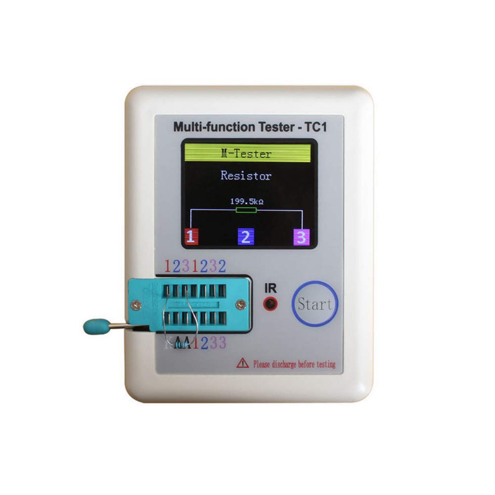
Image 6.2: A measurement result displayed on the Treedix LCR-TC1 screen. The tester has identified a resistor and shows its value as 199.5 kΩ, along with the connected pins (1, 2, 3).
6.2 Supported Component Types and Ranges
- Transistors: NPN, PNP, N-channel MOSFET, P-channel MOSFET. Detects gain (hFE), V_f, and pinout.
- Diodes: Single diodes, dual diodes. Measures forward voltage drop.
- Zener Diodes: Detection range 0.01V - 30V.
- Thyristors/TRIACs: IGT < 6mA.
- Resistors: 0.01 Ω - 50 MΩ.
- Capacitors: 25 pF - 100 mF. Measures capacitance and ESR (Equivalent Series Resistance).
- Inductors: 0.01 mH - 20 H.
- Batteries: Voltage measurement range 0.1V - 4.5V (for measurement, not power source).
6.3 Infrared (IR) Decoding
The tester can detect infrared waveforms. Point an IR remote control towards the IR sensor on the device and press a button. The tester will display the decoded IR signal data.
6.4 Automatic Shutdown
The device will automatically shut down after a period of inactivity to conserve battery power. To manually shut down the device, press and hold the 'Start' button.
7. Maintenance
- Cleaning: Use a soft, dry cloth to clean the device. Do not use abrasive cleaners or solvents.
- Storage: Store the tester in a cool, dry place away from direct sunlight and extreme temperatures.
- Battery Care: Recharge the battery regularly, even if the device is not in frequent use, to maintain battery health. Avoid fully discharging the battery for extended periods.
- Test Leads: Inspect test hooks and cables periodically for any signs of wear or damage. Replace if necessary.
8. Troubleshooting
| Problem | Possible Cause | Solution |
|---|---|---|
| Device does not power on. | Low or depleted battery. | Charge the device using the USB cable. |
| Incorrect or no measurement displayed. | Component not properly connected; Component damaged; Capacitor not discharged; Device needs calibration. | Ensure leads are firmly connected. Check component for damage. Discharge capacitors before testing. Perform calibration (Section 5.3). |
| "Unknown or damaged part" message. | Component is outside measurement range; Component is faulty; Component is still in-circuit. | Verify component type and expected values. Ensure component is isolated from any circuit. |
| Screen is dim or flickering. | Low battery. | Recharge the device. |
9. Specifications
| Parameter | Value |
|---|---|
| Display | 1.8 inch TFT Color Screen |
| Diode Range | < 4.5V |
| Transistor Detect Area | 0.01 - 4.5V |
| Zener Diode Detect Area | 0.01 - 30V |
| Triac Range | IGT < 6mA |
| Capacitance Measurement | 25 pF - 100 mF |
| Resistance Measurement | 0.01 Ω - 50 MΩ |
| Inductance Measurement | 0.01 mH - 20 H |
| Battery Measurement Range | 0.1 - 4.5V |
| Power Mode | Rechargeable Lithium Battery (Included) |
| Dimensions (L x W x H) | Approx. 90 x 50 x 25 mm (3.54 x 1.96 x 0.98 inches) |
| Item Weight | Approx. 0.1 kg (3.52 ounces) |
| Model Number | TRX2-0151 |
| UPC | 765756508568 |
10. Warranty Information
Specific warranty details for the Treedix LCR-TC1 Multi-Function Tester are not provided in this manual. Please refer to the product packaging or the official Treedix website for the most current warranty policy.
11. Customer Support
For technical assistance, troubleshooting beyond this manual, or inquiries regarding your Treedix LCR-TC1 Multi-Function Tester, please visit the official Treedix website or contact their customer support channels. Contact information can typically be found on the product packaging or the brand's online store.


