1. Introduction
The UNI-T UT682D Wire Tracker is a professional tool designed for efficient cable tracking and testing. It consists of two main units: a transmitter (Toner) and a receiver (Probe). This device is capable of tracking various types of cables, including Ethernet, telephone, and power cables, without requiring insulation removal. It is an essential tool for debugging communication cables, audio/video cables, and for checking continuity and polarity on telephone lines.

Figure 1: UNI-T UT682D Wire Tracker, showing the Probe (left) and Toner (right) units with connecting cables.
2. Safety Information
Please read and understand all safety warnings and operating instructions before using this product. Failure to follow these instructions may result in electric shock, fire, or serious injury.
- Do not use the device on live circuits with voltage exceeding the specified limits (60V DC).
- Ensure proper battery installation and replacement.
- Keep the device away from water and moisture.
- Do not attempt to disassemble or modify the device. Refer all servicing to qualified personnel.
- Use the device only for its intended purpose as described in this manual.
- Always wear appropriate personal protective equipment (PPE) when working with electrical systems.
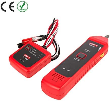
Figure 2: The UNI-T UT682D Wire Tracker displaying CE and RoHS compliance, indicating adherence to European safety and environmental standards.
3. Product Overview
The UT682D consists of two main units: the Transmitter (Toner) and the Receiver (Probe).
3.1 Transmitter (Toner)
The Toner unit generates the signal that is sent through the cable. It features indicators for Tone, Power, and Continuity. It connects to the cable using alligator clips or RJ11/RJ45 connectors.
3.2 Receiver (Probe)
The Probe unit detects the signal generated by the Toner. It has a "Power" button and a "Press to Test" button. The signal strength is indicated by LEDs.

Figure 3: Rear view of the UNI-T UT682D Wire Tracker, showing battery compartments and general construction.
4. Setup
4.1 Battery Installation
Both the Transmitter and Receiver units require 9V batteries for operation.
- Locate the battery compartment cover on the back of each unit.
- Open the cover.
- Insert a 9V battery, ensuring correct polarity (+/-).
- Close the battery compartment cover securely.
Note: The product specifications indicate "1 LR41 requires batteries" and "9V battery x 2" in different sections. For the main units, 9V batteries are typically used. Please refer to the physical product for exact battery type if there is any discrepancy.
5. Operating Instructions
5.1 Wire Tracking
This function allows you to locate a specific wire within a bundle or trace its path.
- Connect the Transmitter (Toner) to the cable you wish to track using the appropriate connector (RJ11 for telephone, RJ45 for Ethernet, or alligator clips for other wires).
- Turn on the Transmitter. The "Tone" indicator should light up.
- Turn on the Receiver (Probe) by pressing the "Power" button.
- Move the tip of the Probe along the suspected cable path. The Probe will emit an audible tone and/or illuminate LEDs when it detects the signal from the Transmitter.
- Follow the strongest signal to trace the cable's route.
5.2 Telephone Line Polarity Check
The UT682D can check the polarity of telephone lines.
- Connect the Transmitter to the telephone line using the RJ11 connector.
- Observe the polarity indication on the Transmitter.
5.3 Continuity Test
Use this function to check for breaks or short circuits in a cable.
- Connect the Transmitter to both ends of the cable (or one end and a known good ground).
- Turn on the Transmitter.
- If the "Continuity" indicator lights up, the cable has continuity. If not, there is a break or open circuit.
6. Maintenance
6.1 Cleaning
Wipe the device with a dry, soft cloth. Do not use abrasive cleaners or solvents.
6.2 Battery Replacement
Replace batteries when the power indicator dims or the device stops functioning correctly. Follow the battery installation steps in Section 4.1. Dispose of used batteries responsibly.
6.3 Storage
When not in use for extended periods, remove the batteries to prevent leakage. Store the device in a cool, dry place, away from direct sunlight and extreme temperatures.
7. Troubleshooting
| Problem | Possible Cause | Solution |
|---|---|---|
| No power/Device not turning on | Dead or incorrectly installed batteries | Replace batteries, ensure correct polarity. |
| No signal detected by Probe | Transmitter not on, cable not connected, cable break, signal too weak | Ensure Transmitter is on and connected. Check cable for damage. Move Probe closer to the cable. |
| Inaccurate tracking | Interference from other cables/devices, incorrect connection | Minimize interference sources. Ensure secure connection. |
| Continuity test fails | Cable break, poor connection | Check cable for physical damage. Ensure secure connections at both ends. |
8. Specifications
The following table outlines the technical specifications for the UNI-T UT682D Wire Tracker.

Figure 4: Technical specifications for the UT682D Wire Tracker, including wire types, tracking distance, power, and environmental conditions.
| Feature | Specification |
|---|---|
| Model | UT682D |
| Wire Types | Telephone line, Twisted-pair, Electric wire |
| Telephone Lines Tracking Distance | ≥3000m |
| Polarity Indication for Telephone Lines | DCV function, range: ±(5V~52V) |
| Telephone Lines and LAN Cables Distinction | Jacks distinction |
| Transmitter Output Voltage | 8V DC (with a new battery) |
| Transmitter Power Supply | 9V battery |
| Receiver Power Supply | 9V battery |
| Max Receiver Standby Current | ~10mA |
| Max Receiver Operating Current | <40mA (AC, RMS) |
| Transmitter Input Voltage Protection | 60V DC |
| Operating Temperature | 0~40°C |
| Storage Temperature | -10~50°C |
| Operating Humidity | 20~75% RH |
| Storage Humidity | 10~90% RH |
| Altitude | ≤2000m |
| Product Color | Red and grey |
| Product Net Weight | Transmitter-150g, Receiver-130g |
| Product Size (Transmitter) | 74mm x 68mm x 28mm |
| Product Size (Receiver) | 208mm x 47mm x 33mm |
| Standard Accessories | 9V battery x 2, English manual |
| Certifications | CE, ISO 9001 |
| Measurement Accuracy | +/-0.5% |
9. Warranty and Support
UNI-T products are manufactured to high-quality standards and are warranted against defects in materials and workmanship. For specific warranty terms and conditions, please refer to the warranty card included with your product or contact your local UNI-T distributor.
For technical support, troubleshooting assistance, or service inquiries, please contact the retailer where you purchased the product or visit the official UNI-T website for contact information.


