
1. Introduction
The LIDER Motion Sensor Switch LPS-1P-WWP is designed to automatically control lighting based on occupancy or vacancy in a room. Utilizing Passive Infrared (PIR) technology, it detects motion to provide hands-free lighting, enhancing convenience and promoting energy savings. This switch is suitable for single-pole applications and does not require a neutral wire for installation.
2. Safety Information
WARNING: RISK OF ELECTRIC SHOCK. Improper installation can result in serious injury or death.
- Always turn off power at the circuit breaker or fuse box before installation, servicing, or removing the switch.
- Ensure all wiring connections are secure and comply with local electrical codes.
- This device is for indoor use only.
- Do not use with loads exceeding specified ratings.
- If you are unsure about any part of these instructions, consult a qualified electrician.
- The LIDER Motion Sensor Switch LPS-1P-WWP is UL Listed, ensuring compliance with safety standards.
3. Package Contents
- 1 x LIDER Motion Sensor Switch (LPS-1P-WWP)
- 1 x LIDER Wall Plate (LWP-31M-W)
- Installation Screws
4. Specifications
| Model | LPS-1P-WWP |
| Voltage | 120VAC, 60 Hz |
| Load Capacity | 300W Tungsten, 150W LED/CFL |
| Sensor Type | Passive Infrared (PIR) |
| Field of View | 180 degrees |
| Coverage Area | Up to 1200 sq ft (max) |
| Wiring | Single-pole only, No neutral wire required |
| Operating Temperature | 32-104ºF (0-40ºC) |
| Certifications | UL Listed |
5. Installation
Follow these steps carefully to install your LIDER Motion Sensor Switch:
- Turn Off Power: Locate the circuit breaker or fuse that controls the light switch you are replacing. Turn off the power completely to avoid electrical shock. Verify power is off using a voltage tester.
- Remove Old Switch: Unscrew and carefully pull the old switch from the wall box. Disconnect the wires from the old switch.
- Identify Wires: You should have three wires:
- LINE Wire: Carries power from the circuit breaker.
- LOAD Wire: Carries power to the light fixture.
- GROUND Wire: Bare copper or green insulated wire.
Note: This switch does not require a neutral wire.
- Wire the New Switch: Connect the wires from the wall box to the LIDER Motion Sensor Switch as follows:
- Connect the LINE wire to the terminal labeled 'LINE' on the switch.
- Connect the LOAD wire to the terminal labeled 'LOAD' on the switch.
- Connect the GROUND wire to the green ground screw on the switch.
Ensure all wire connections are tight and secure.
- Mount the Switch: Carefully push the wired switch back into the wall box. Secure it with the provided screws.
- Attach Wall Plate: Snap the included LIDER wall plate onto the switch.
- Restore Power: Turn the power back on at the circuit breaker. The switch will require 1-2 minutes to warm up after installation.

6. Operating Instructions
The LIDER Motion Sensor Switch offers two operating modes: Occupancy and Vacancy. The mode can be selected using the OCC/VAC switch located under the face of the device.
6.1. Occupancy Sensor Mode (Auto ON, Auto OFF)
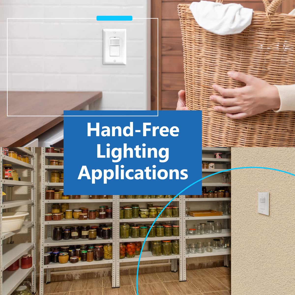
In this mode, the lights will automatically turn ON when motion is detected and automatically turn OFF after a set time delay when no motion is detected. This mode is ideal for high-traffic areas where hands-free operation is desired, such as hallways, bathrooms, or utility rooms.
6.2. Vacancy Sensor Mode (Manual ON, Auto OFF)
In this mode, the lights must be turned ON manually by pressing the switch button. They will then automatically turn OFF after a set time delay when no motion is detected. This mode is suitable for areas where manual control over initial light activation is preferred, such as bedrooms or offices, while still benefiting from automatic turn-off for energy savings.

7. Adjusting Settings
The sensor range and time delay settings can be adjusted to customize the switch's performance. These adjustments are made using dials located under the switch's faceplate.
- Access Settings: Carefully remove the outer wall plate, then gently pry off the switch's face cover to reveal the adjustment dials.
- Adjust Sensor Range: The 'RANGE' dial allows you to set the motion detection sensitivity. Options typically include 25%, 50%, 75%, and 100%. Adjust this based on the size of the room and desired detection area.
- Adjust Time Delay: The 'TIME' dial sets how long the lights remain ON after the last detected motion. Available options are 15 seconds (Test mode), 5 minutes, 10 minutes, 20 minutes, and 30 minutes. The 15-second 'Test' mode is useful for verifying sensor operation after installation.
- Reassemble: Once settings are adjusted, snap the face cover back onto the switch, then reattach the wall plate.


8. Troubleshooting
If you experience issues with your LIDER Motion Sensor Switch, refer to the following common problems and solutions:
| Problem | Possible Cause | Solution |
|---|---|---|
| Lights do not turn ON automatically. |
|
|
| Lights do not turn OFF. |
|
|
| Lights are too sensitive or not sensitive enough. | Sensor range setting is incorrect. | Adjust the 'RANGE' dial under the faceplate to increase or decrease sensitivity. |
9. Maintenance
The LIDER Motion Sensor Switch requires minimal maintenance. To clean the device, ensure power is turned off at the circuit breaker. Use a soft, damp cloth to wipe the surface. Do not use abrasive cleaners, solvents, or harsh chemicals, as these can damage the finish or internal components.
10. Warranty and Support
10.1. Warranty
This LIDER Motion Sensor Switch LPS-1P-WWP is covered by a 1-year limited warranty from the date of purchase. This warranty covers defects in materials and workmanship under normal use. It does not cover damage resulting from improper installation, misuse, abuse, or unauthorized modifications.
10.2. Customer Support
For technical assistance, troubleshooting, or warranty claims, please contact LIDER customer service. You can find contact information and additional resources by visiting the official LIDER store or website: