1. Important Safety Information
Please read this manual thoroughly before installation, operation, or maintenance of the ATO Single Phase Output VFD. Failure to follow these instructions may result in serious injury or equipment damage. Always observe proper electrical safety procedures.
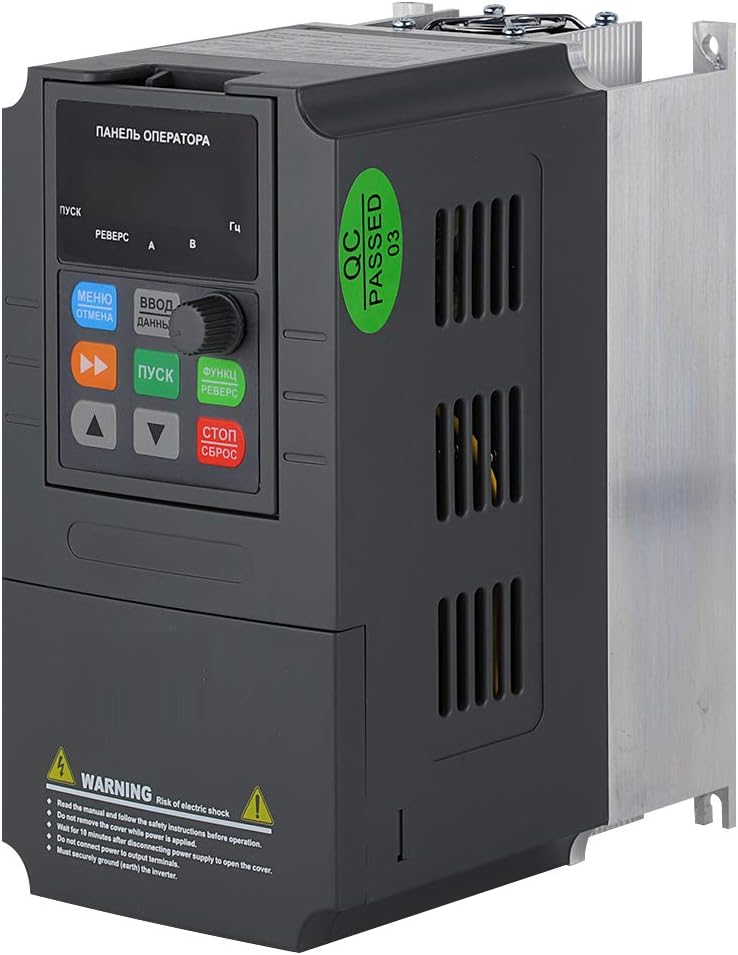
- Risk of Electric Shock: Do not remove the cover while power is applied. Wait for at least 10 minutes after disconnecting power supply to open the cover, allowing capacitors to discharge.
- Do not connect power to output terminals (U, V, W).
- Ensure proper earth (ground) connection for the inverter.
- The single-phase motor should not be adjusted to run based on a lower frequency than 80% of its rated frequency for a long time, otherwise the motor may fail.
- ATO VFD cannot be used as a power source; it can only be directly connected to an induction motor to control the motor speed.
- Single-phase VFD cannot control the motor in reverse. Refer to the motor nameplate instructions for reverse operation if applicable.
- If the single-phase VFD has been restored to factory settings, ensure that phase-loss protection is disabled by setting PA.13 = 0.
2. Setup and Wiring
Proper wiring is crucial for safe and effective operation. Always ensure power is disconnected before making any connections.
2.1 Product Overview


2.2 Basic Wiring Diagram

2.3 Power Supply Connection
Connect the single-phase AC 220V (±15%) power supply to the L and N terminals of the VFD. The input frequency should be 47~63Hz.
2.4 Motor Connection
For single-phase motors, connect the motor wires to the U and V terminals of the VFD. The W terminal should be left unconnected. For 3-phase motors, connect to U, V, W.
2.5 Braking Resistor Connection
If using a braking resistor, connect it between the P+ and PB terminals only. Incorrect wiring of the braking resistor may cause serious damage to the VFD control board.
2.6 Control Terminal Wiring (Self-Lock Push Button Example)
To control the VFD using an external self-lock push button for forward running, connect one normally open (NO) terminal of the push button to the X1 (FWD) terminal on the VFD, and the other terminal of the push button to the common (COM) input.
Video 2.1: VFD Two-Wire Control Wiring with Push Button for Forward Motor. This video demonstrates the step-by-step process of wiring a self-locking push button to the VFD for forward motor control, including power and motor connections.
Video 2.2: How to wire an inverter up? This video provides a general guide on connecting an inverter, covering essential wiring steps for proper setup.
3. Operating Instructions
3.1 VFD Programming for Control
After wiring, the VFD needs to be programmed to recognize the external control switch. The following parameters are essential:
- P0.01 = 1: Main frequency source selection (Digital setting 2, UP/DOWN can modify, retentive at power failure).
- P0.03 = 1: Command source selection (Terminal control, LED on).
- P3.00 = 1: Input terminal X1 function selection (Forward RUN).
- P3.14 = 1: Terminal command mode (Two-line mode 2).
Video 3.1: ATO VFD Parameter Setting for 1 Phase & 3 Phase Motor. This video guides through the essential parameter settings for both single-phase and three-phase motors on the ATO VFD.
Video 3.2: ATO 110V Input VFD: Setting Base Frequency to 60Hz. This video demonstrates how to set the base frequency to 60Hz on an ATO 110V input VFD.
3.2 Motor Speed Adjustment
Once the VFD is programmed, you can adjust the motor speed by turning the panel speed control knob (potentiometer) on the VFD's digital operator panel. This changes the output frequency, thereby regulating the motor speed.
Video 3.3: Control ATO VFD with potentiometer & button (VI port). This video illustrates how to control the ATO VFD using a potentiometer and a button connected to the VI port for speed adjustment.
Video 3.4: 4-20mA speed control on ATO VFD (CI port). This video demonstrates how to implement 4-20mA speed control on the ATO VFD using the CI port.
Video 3.5: How to Control VFD with 0-10V (CI Port). This video explains the process of controlling the VFD's speed using a 0-10V signal through the CI port.
4. Maintenance
Regular maintenance ensures the longevity and optimal performance of your VFD. Always disconnect power before performing any maintenance.
- Cleaning: Keep the VFD clean and free from dust and debris. Use a soft, dry cloth for cleaning. Do not use liquid cleaners.
- Ventilation: Ensure proper ventilation around the VFD to prevent overheating. Regularly check that the cooling fan is operating correctly and not obstructed.
- Connections: Periodically check all wiring connections for tightness and signs of wear or corrosion.
- Environmental Conditions: Ensure the VFD is operated within its specified environmental conditions (temperature, humidity, etc.) to prevent damage.
5. Troubleshooting
If you encounter issues with your VFD, refer to the following common problems and solutions:
- Motor Not Starting:
- Check power supply connections (L, N).
- Verify motor wiring (U, V, W).
- Ensure control parameters (P0.01, P0.03, P3.00, P3.14) are set correctly for your control mode.
- If using a single-phase motor, ensure it is not adjusted to run below 80% of its rated frequency for extended periods.
- VFD Overload Alarm:
- Ensure the rated current of the VFD is greater than the rated current of your motor.
- Ensure the rated power of the VFD is greater than the rated power of your motor, preferably by at least one level (e.g., for a 5HP motor, use a 7.5HP VFD).
- Motor Not Reversing (Single-Phase):
- Single-phase VFDs cannot control motor reversal. Refer to your motor's nameplate for specific instructions on reversing its direction.
- Settings Lost After Power Cycle:
- Ensure P0.01 is set to '1' (Digital setting 2) to retain settings after power failure.
6. Specifications
| Feature | Specification |
|---|---|
| Model | 2 HP 1.5 kW |
| Input Voltage | Single Phase AC 220V±15% |
| Input Frequency | 47~63Hz |
| Output Voltage | 0~Single Phase AC 220V |
| Output Frequency | 0~1000Hz |
| Rated Current | 9.6A |
| Operation Command Mode | Keypad control, Terminal control, Serial communication control |
| Display Type | LCD |
| Material | Metal |
| Product Dimensions | 5.84 x 3.07 x 5.84 inches |
| Item Weight | 2.73 pounds (1.24 Kilograms) |
7. Customer Support
If you have any questions or require assistance with your ATO VFD, please do not hesitate to contact us. We are committed to providing prompt support and will respond within 12 hours.
For additional resources and product information, visit the ATO Store on Amazon.


