
G-Force G0321
G-FORCE Mini Break-in System+R G0321 User Manual
Model: G0321 | Brand: G-FORCE
Introduction
The G-FORCE Mini Break-in System+R is a compact and efficient device designed to optimize the performance of small electric motors and gears, particularly for 1/24 to 1/32 scale models. It allows for precise control over the break-in process, ensuring your components operate at their peak potential. This manual provides essential information for the safe and effective use of your device.
Safety Precautions
- Always read this manual thoroughly before use.
- Keep the device away from water and moisture to prevent electric shock or malfunction.
- Do not disassemble or modify the device. Unauthorized modifications can lead to damage or injury.
- Use only the specified power sources (AAA batteries or a 6V/2A AC adapter).
- Ensure proper ventilation during operation to prevent overheating.
- Keep out of reach of children.
- Disconnect the power source when not in use or during maintenance.
Package Contents
Please check that all items are present in your package:
- G-FORCE Mini Break-in System+R Main Unit
- Connection Cables (Red and Black Alligator Clips)
- Instruction Manual (This document)
Note: AAA batteries and AC adapter are sold separately and are not included with this product.
Product Overview
Familiarize yourself with the components of your Mini Break-in System+R.

Figure 1: Front view of the G-FORCE Mini Break-in System+R. It features a digital display for timer and output voltage, a large rotary dial for adjustments, a reverse button, and input/output ports.

Figure 2: Side view highlighting the convenient integrated handle for portability.
Setup
- Power Source Connection: Insert 4 x AAA alkaline or rechargeable batteries into the battery compartment, or connect a 6V/2A AC adapter (both sold separately) to the DC INPUT 6V port on the side of the unit.
- Motor/Chassis Connection: Connect the red alligator clip cable to the positive (+) terminal of your motor or chassis, and the black alligator clip cable to the negative (-) terminal. Ensure a secure connection.
- Secure the Component: Use the integrated Velcro-type belt on the top surface of the unit to securely fix your motor or chassis in place during the break-in process. This prevents movement and ensures stable operation.
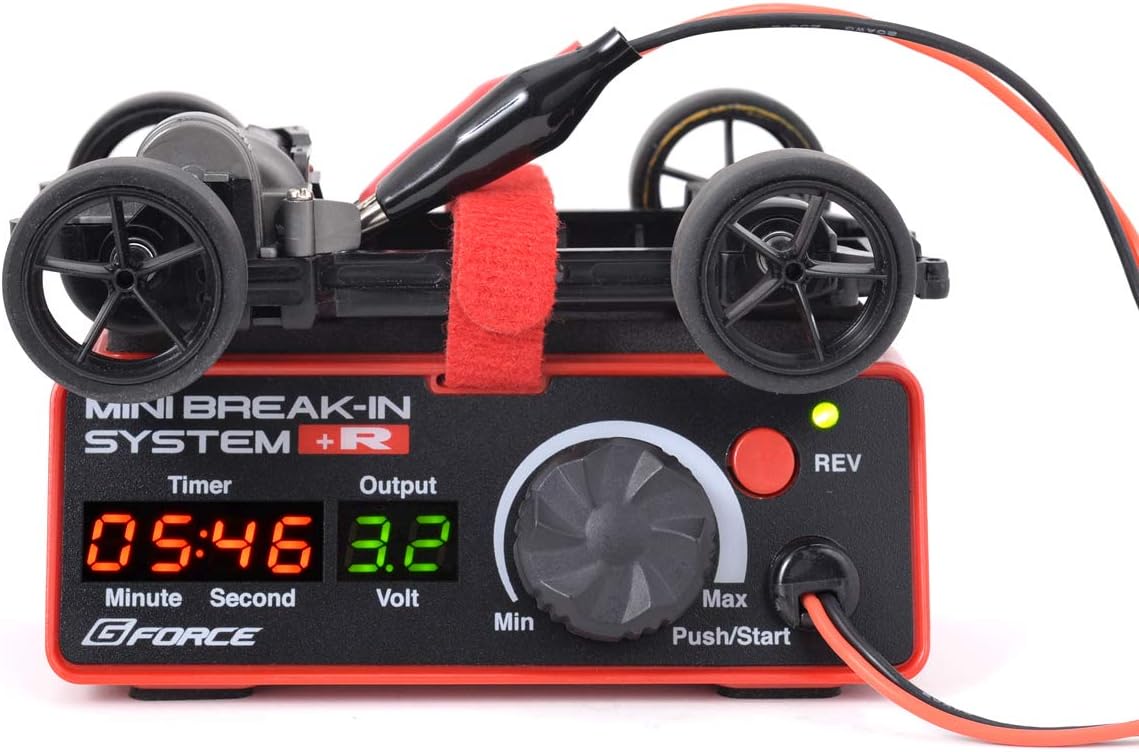
Figure 3: A mini 4WD chassis secured on the unit's top surface with the Velcro strap, ready for break-in.

Figure 4: A standalone motor secured on the unit, demonstrating direct motor break-in.
Operating Instructions
- Power On: Once the power source is connected, the unit will automatically power on and display the current settings.
- Setting Output Voltage: Rotate the large dial to adjust the output voltage. The voltage can be set in 0.1V increments, from a minimum to a maximum of 6.0V. The current output voltage is displayed on the screen.
- Setting Timer: Press the rotary dial to cycle through timer settings. Rotate the dial to adjust the desired break-in duration in minutes and seconds. The off-timer function will automatically stop the process once the set time elapses.
- Start/Stop Operation: Press the rotary dial (labeled "Push/Start") to start or stop the break-in process.
- Reverse Rotation: Press the "REV" button to switch the motor's rotation direction between forward and reverse. This is useful for breaking in both directions.

Figure 5: The unit in operation with a mini 4WD chassis, demonstrating its application for model components.

Figure 6: The unit breaking in a mini 4WD chassis, with the car body shown separately.
Maintenance
- Cleaning: Wipe the unit with a soft, dry cloth. Do not use harsh chemicals or abrasive cleaners.
- Storage: Store the device in a cool, dry place away from direct sunlight and extreme temperatures.
- Battery Removal: If storing for an extended period, remove the AAA batteries to prevent leakage.
Troubleshooting
| Problem | Possible Cause | Solution |
|---|---|---|
| Device does not power on. | No power source connected or batteries are depleted/incorrectly inserted. | Ensure batteries are correctly inserted with proper polarity, or connect a functional AC adapter. |
| Motor does not spin. | Incorrect connection, insufficient voltage, or motor issue. | Check alligator clip connections to the motor/chassis. Increase the output voltage using the dial. Test the motor separately if possible. |
| Displayed voltage differs from multimeter reading. | The device uses pulse control to vary the effective voltage. Standard multimeters may not accurately read pulsed DC voltage. | This is normal operation. The displayed voltage is the effective voltage controlled by the unit. For accurate measurement, a multimeter capable of reading PWM (Pulse Width Modulation) signals is required. |
| Timer function not working. | Timer not set or not activated. | Ensure the timer is set to a duration greater than zero and the break-in process is started. |
Specifications
- Model Number: G0321
- Power Source: 4 x AAA alkaline batteries (sold separately) / 4 x AAA rechargeable batteries (sold separately) / AC adapter 6V/2A (sold separately)
- Operating Voltage: 4.8V - 6.0V
- Adjustable Output Voltage: 0.1V - 6.0V (in 0.1V increments)
- Dimensions: 112 mm (W) x 47 mm (D) x 45 mm (H)
- Weight: Approximately 105g (excluding batteries)
- Features: Forward/Reverse rotation switch, Off-timer function, Rotary dial operation, Velcro-type belt for securing components.
- Country of Origin: China
- Release Date: June 19, 2020
Warranty and Support
Information regarding product warranty and direct manufacturer support is not available in the provided product details. Please refer to the retailer's return policy or contact the point of purchase for assistance with any warranty claims or technical support inquiries.
Related documentsG0321


Ask a question about this manual
Ask about setup, troubleshooting, compatibility, parts, safety, or missing instructions. Manuals+ will review the question and use this page’s manual context to help answer it.