
diymore LCR-TC1
Contents
Diymore LCR TC1 ESR Transistor Tester Multifunction Tester User Manual
Brand: diymore | Model: LCR-TC1
Important Safety Information
WARNING: The built-in Li-ion battery must not be immersed in water or placed near a heat source. For your personal safety, always observe the specifications and precautions for Li-ion batteries.
CAUTION: Always discharge capacitors before connecting them to the tester! The tester can be damaged if capacitors are not discharged. It is not recommended to use the tester to measure batteries with voltage above 4.5V, as this may damage the tester.

Image: Important safety warnings regarding battery and capacitor handling.
Product Overview
The Diymore LCR TC1 is a versatile multifunction tester designed for identifying and measuring various electronic components. It features a clear TFT graphic display for easy reading of measurement results.
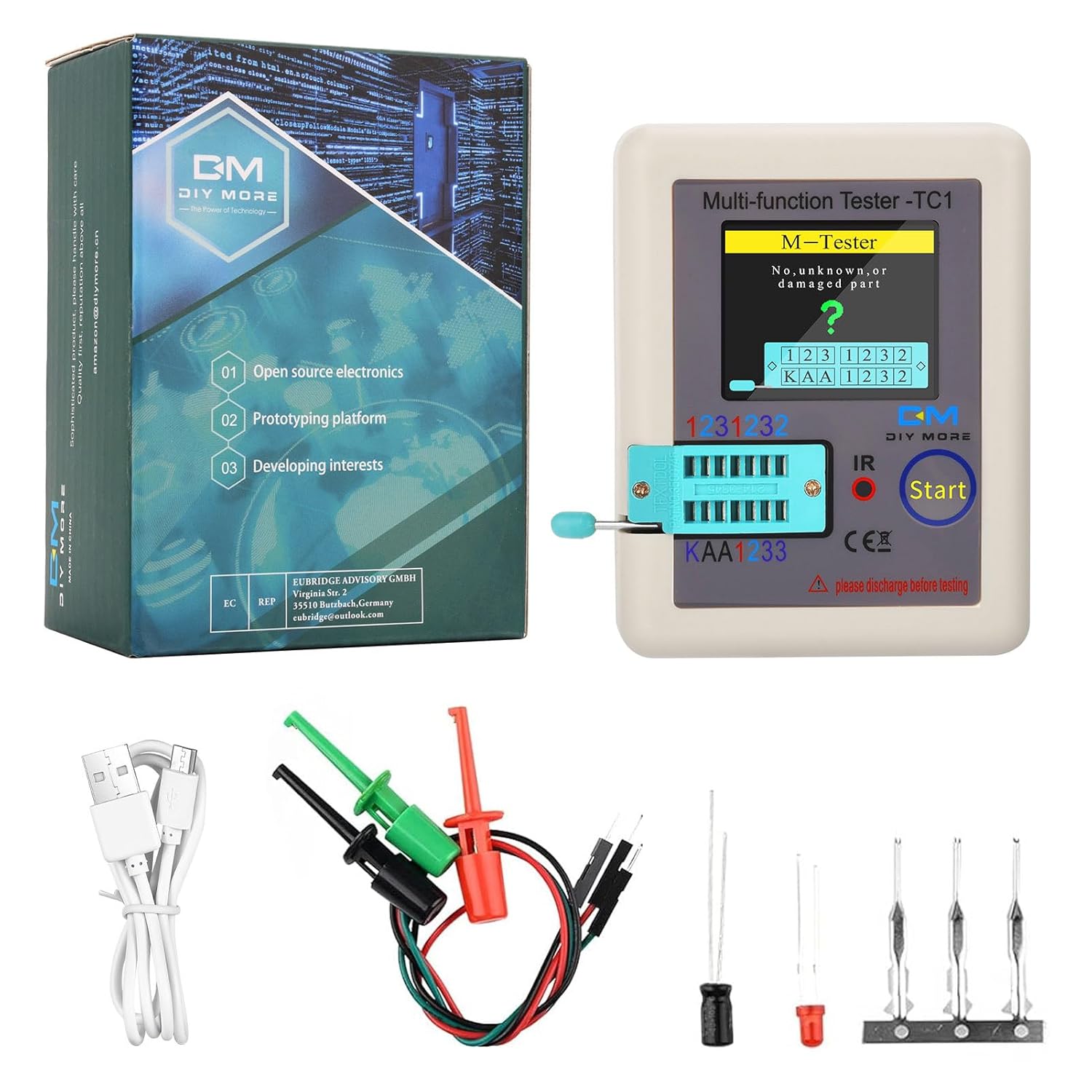
Image: The Diymore LCR TC1 tester, its retail box, a USB charging cable, and test clips.
Key Features:
- Multifunction Testing: Capable of detecting NPN and PNP transistors, capacitors, resistors, diodes, triodes, N-channel and P-channel MOSFETs, JFET, IGBT, Triac, and battery voltage.
- TFT Graphic Display (160x128): Provides clear, graphical display of measurement results. Supports both Chinese and English languages.
- IR Decoder: Allows for decoding of infrared remote control signals, displaying the data code and infrared waveform.
- Charging Indicator LED: A red LED indicates charging status, turning green when fully charged.
- Automatic Calibration: Simplifies setup with an automatic calibration function.

Image: A detailed diagram highlighting the 160x128 TFT display, IR receiver window, multifunction key, transistor test area, Zener diode test area, Micro USB charging interface, and charge indicator LED.
Setup
Initial Charging:
Before first use, ensure the device is fully charged. Connect the provided USB cable to the Micro USB charging interface on the tester and a suitable 4.5V power source. The charging indicator LED will glow red during charging and turn green once fully charged.
Note: Do not use a charging input voltage higher than 4.5V to prevent damage to the tester.
Component Placement:
The test socket is divided into a transistor test area and a Zener diode test area. Ensure components are placed in the correct area for accurate measurement.

Image: A visual guide for correctly placing components into the test socket for measurement.
Automatic Calibration:
To calibrate the tester, short-circuit the three test sockets. Briefly press the multifunction button. The tester will automatically calibrate. Follow any on-screen prompts during the calibration process; no further operations are required until prompted to disconnect the short circuit.

Image: The tester screen displaying the calibration process, with test pins shorted.
Operating Instructions
Power On and Measurement:
When the tester is off, briefly press the multifunction button. The tester will power on and automatically begin a measurement cycle.

Image: The tester displaying the results of a component test, showing component type and pinout.
Automatic and Manual Shutdown:
- Automatic Shutdown: After a component test or infrared decoding is complete, the tester will automatically shut down after a set timeout period. The factory default timeout is 20 seconds. This timeout can be adjusted (10, 15, 20, 25 seconds) by shorting jumpers inside the device. This requires opening the casing and soldering, and static ESD protection is recommended.
- Manual Shutdown: To force shutdown at any time, including during a measurement, long-press the multifunction button.
Component Testing Procedure:
With the tester off or after a completed test, insert the component's pins into the appropriate test area of the socket. Press the locking handle down. Briefly press the multifunction button. The tester will automatically measure the component and display the graphical results on the screen.

Image: The tester displaying the capacitance and Equivalent Series Resistance (ESR) of a capacitor.

Image: The tester displaying the resistance value of a resistor.
Infrared (IR) Decoding:
After a component detection or at the main screen, point an infrared remote control towards the "IR" light window on the tester. Press a button on the remote control. If successful, the tester will decode the signal and display the data code and infrared waveform.

Image: The tester displaying decoded infrared data and waveform from a remote control.
Maintenance
To ensure the longevity and accurate performance of your Diymore LCR TC1 tester, follow these maintenance guidelines:
- Cleaning: Wipe the device with a soft, dry cloth. Do not use abrasive cleaners or solvents.
- Storage: Store the tester in a cool, dry place away from direct sunlight and extreme temperatures.
- Battery Care: Avoid fully discharging the battery frequently. Recharge the device when the battery level is low. If storing for extended periods, charge the battery to approximately 50% every few months.
- Capacitor Discharge: Always ensure capacitors are fully discharged before connecting them to the tester to prevent damage to the device.
Troubleshooting (Frequently Asked Questions)

Image: A visual representation of common questions and answers regarding the tester's functionality.
Can this transistor tester measure Darlington transistors?
The output current of the tester is 6 mA, and the voltage is less than 5 V. High-power IGBTs, Thyristors, and Darlington transistors cannot be tested.
Can this transistor tester measure hollow coils and power inductors?
Hollow coils and power inductors cannot be measured directly. Please connect the corresponding color ring inductor for testing.
Do I need to discharge the capacitor before measuring it?
Yes, always discharge capacitors before connecting them to the tester. Failure to do so can damage the tester.
How can I distinguish between the two measurement areas?
Triodes, diodes, capacitors, etc., are measured in the "123" area; place them in positions "1" and "3". Zener diodes should be inserted into the "KAA" area for measurement.
Why does the screen show a Zener diode when I measure resistance?
Resistance cannot be measured in the "KAA" area. If you insert a component into the "KAA" area, it will be displayed as a Zener diode.
Why is the resistance measurement inaccurate?
If the measured resistance is less than 10 Ohms, this can cause inaccuracy in the reading.
Specifications
The following table details the technical specifications and measurement ranges for the Diymore LCR TC1 Multifunction Tester:

Image: A comprehensive table outlining component types, their measurable ranges, and parameter descriptions.
| Specification | Value |
|---|---|
| Manufacturer | diymore |
| Part Number | D051055 |
| Item Weight | 120 g |
| Package Dimensions | 11.2 x 8.4 x 4.9 cm |
| Batteries | 1 Lithium-Polymer battery required (included) |
| Model Number | LCR-TC1 |
| Color | LCR-TC1 |
| Style | Modern |
| Material | TFT |
| Power Source | Battery Powered |
| Measurement Accuracy | 0.1 |
| Included Components | Transistor-Tester |
| First Available Date | 20. May 2020 |

Image: The physical dimensions of the Diymore LCR TC1 tester, showing its length, width, and height.
Warranty and Support
Warranty Information:
Specific warranty details are typically provided at the point of purchase or within the product packaging. Please refer to your purchase receipt or the seller's terms and conditions for warranty coverage.
Customer Support:
If you have any questions, encounter issues, or require assistance with your Diymore LCR TC1 tester, please feel free to contact the seller or Diymore customer support. Contact information can usually be found on the product packaging or the seller's page where the product was purchased.
Ask a question about this manual
Ask about setup, troubleshooting, compatibility, parts, safety, or missing instructions. Manuals+ will review the question and use this page’s manual context to help answer it.