1. Introduction
This manual provides essential instructions for the installation, operation, and maintenance of the BFT SB-BAT P125002 24V DC Battery Backup Kit. This kit is designed to ensure continuous operation of compatible BFT gate openers during temporary power outages. Please read this manual thoroughly before proceeding with installation or use.
2. Product Overview
The BFT SB-BAT P125002 is a 24V DC battery backup system that integrates with specific BFT gate operators. It includes a smart charger board that manages battery charging when main power is available and automatically switches to battery power when the main supply is interrupted.

Figure 1: Overview of the BFT SB-BAT P125002 Battery Backup Kit, showing the product box, two batteries, wiring, and mounting hardware.
2.1. Kit Components
- 2x 12V 1.2Ah Sealed Lead-Acid Batteries
- Smart Charger Board
- Wiring Harnesses
- Battery Holder/Mounting Base
- Mounting Brackets
- Fasteners (screws, keys)
- Instruction Manual (this document)
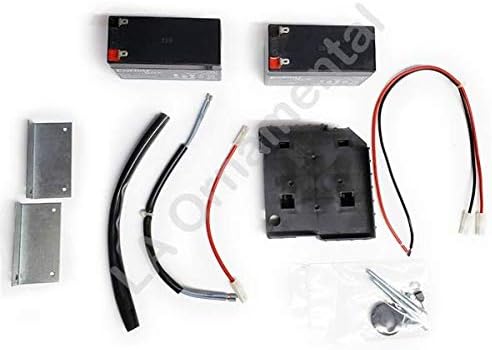
Figure 2: Detailed view of the BFT SB-BAT P125002 kit components, including batteries, wiring, mounting brackets, and the battery holder.
3. Compatibility
This battery backup system is compatible with the following BFT gate operator series:
- Deimos BT series of slide gate operators
- VIRGO - LINX
- EOS-SCE
- HYDRA N
- DEIMOS BT-QSC D-NETTUNO S
- SB BAT/SB CARBAT (DEIMOS BT-SB 300)
- BT BAT 2 (URANO BT ARES 1000 & ARES 1500)
- NETTUNO B
- VENERE D
- ARGO
- LIBRA C MA - LIBRA C LX
Ensure your gate operator model is listed above for proper functionality.
4. Setup and Installation
Installation of the BFT SB-BAT P125002 kit is designed to be straightforward. However, it is recommended that installation be performed by a qualified technician to ensure safety and correct operation. Always disconnect main power to the gate operator before beginning installation.
4.1. Safety Precautions
- Disconnect Power: Always turn off the main power supply to the gate operator before installation or maintenance.
- Proper Tools: Use appropriate tools for electrical connections and mounting.
- Wiring: Ensure all wiring connections are secure and correctly polarized.
- Environment: Install the kit in a dry, protected location, away from direct weather exposure.
4.2. Installation Steps (General Guidelines)
- Mount the Battery Holder: Secure the battery holder/mounting base within the gate operator's control box or an appropriate enclosure using the provided mounting brackets and fasteners. Ensure it is stable and accessible.
- Insert Batteries: Place the two 12V 1.2Ah batteries into the battery holder.
- Connect Batteries: Connect the batteries in series to achieve 24V DC, following the wiring diagram provided with your specific gate operator or the kit's smart charger board. Ensure correct polarity.
- Connect Smart Charger Board: Integrate the smart charger board into the gate operator's control unit. Refer to your gate operator's manual for the specific connection points for the battery backup system.
- Secure Wiring: Route and secure all wiring to prevent pinching or damage.
- Restore Power: Once all connections are verified and secure, restore main power to the gate operator. The smart charger board will begin charging the batteries.
- Test System: Perform a power outage simulation to verify the battery backup system activates correctly and powers the gate operator.
5. Operating Instructions
The BFT SB-BAT P125002 operates automatically once installed correctly.
5.1. Normal Operation (Power On)
When main power is supplied to the gate operator, the smart charger board within the SB-BAT kit continuously monitors the battery charge level. It will charge the batteries as needed to maintain them at full capacity.
5.2. Power Outage Operation (Power Off)
In the event of a power outage, the smart charger board automatically detects the loss of main power and switches the gate operator to battery power. The gate operator will then function normally using the stored energy in the batteries. The duration of operation on battery power depends on the frequency of gate usage and the charge level of the batteries.
6. Maintenance
Regular maintenance ensures the longevity and reliability of your battery backup system.
6.1. Battery Recharging
After a power outage, once main power is restored, the smart charger board will automatically begin recharging the batteries. A full recharge typically takes 12 to 14 hours. It is important to allow sufficient time for batteries to fully recharge after use.
6.2. Fuse Check
The system includes a 20A fuse for protection. If the battery backup system fails to operate or charge, inspect the fuse for continuity. Replace with a fuse of the exact same rating if necessary. Always disconnect power before checking or replacing fuses.
6.3. Battery Life and Replacement
Batteries have a finite lifespan. Periodically test the system by simulating a power outage to ensure batteries hold a charge and can power the gate operator. If performance degrades significantly, consider replacing the batteries. Use only recommended replacement batteries (2x 12V 1.2Ah sealed lead-acid).
7. Troubleshooting
If your BFT SB-BAT P125002 battery backup system is not functioning as expected, consider the following:
- No Power During Outage:
- Verify all wiring connections are secure and correct.
- Check the 20A fuse.
- Ensure batteries are fully charged. If recently discharged, allow 12-14 hours for recharging.
- Test battery voltage. If below 20.4V (exhausted battery protection threshold), batteries may need replacement.
- Batteries Not Charging:
- Confirm main power supply to the gate operator is active.
- Check all connections to the smart charger board.
- Inspect the 20A fuse.
- Reduced Operation Time:
- Batteries may be aging and losing capacity. Consider replacement.
- Ensure batteries are fully charged before testing.
For persistent issues, contact BFT technical support or a qualified service technician.
8. Specifications
| Feature | Specification |
|---|---|
| Model Number | P125002 |
| Battery Type | Sealed Lead-Acid |
| Battery Capacity | 2x (12V 1.2Ah) |
| Output Voltage | 24V DC (nominal) |
| Charge Voltage | 27.2V |
| Charge Current | 130mA |
| Battery Recharging Time | 12-14 hours |
| Exhausted Battery Protection Threshold | 20.4V |
| Fuse Rating | 20A |
| Operating Temperature | Data detected with external temperature of: 25°C (77°F) |
9. Warranty and Support
For warranty information, please refer to the documentation provided with your original purchase or contact BFT customer support directly. For technical assistance, installation queries, or troubleshooting beyond the scope of this manual, please contact your authorized BFT dealer or BFT technical support.
BFT Contact Information: Please visit the official BFT website for the most current contact details and support resources.