1. Introduction
This manual provides essential information for the safe and efficient installation, operation, and maintenance of the TURCK C10-A10X/012VDC SPDT Relay. This electromechanical relay is designed for general purpose applications, featuring a single pole double throw (SPDT) contact configuration, a 12VDC coil, and an integrated LED indicator for status monitoring. Please read this guide thoroughly before proceeding with any installation or operation.
2. Safety Information
Always observe the following safety precautions to prevent personal injury or damage to the equipment:
- Electrical Hazard: Ensure all power sources are disconnected before installation, wiring, or maintenance. Only qualified personnel should perform electrical work.
- Voltage and Current Ratings: Do not exceed the specified coil voltage (12VDC) or contact current rating (10 Amps). Overloading can cause damage or fire.
- Proper Wiring: Use appropriate wire gauges and insulation for the intended current and voltage. Ensure all connections are secure to prevent arcing or short circuits.
- Environmental Conditions: Install the relay in an environment free from excessive moisture, dust, corrosive gases, or extreme temperatures.
3. Product Overview
The TURCK C10-A10X/012VDC is a compact general-purpose relay designed for reliable switching in various industrial and control applications. It features a single pole double throw (SPDT) contact arrangement, allowing it to switch one circuit between two different paths. An integrated LED indicator provides visual confirmation of the coil's energized state.
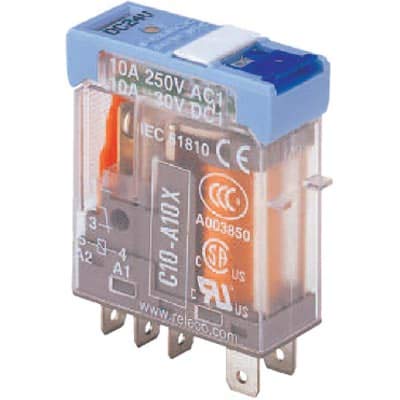
Image 1: Front view of the TURCK C10-A10X/012VDC SPDT Relay. This image displays the compact form factor of the relay, highlighting its terminal pins and the visible LED indicator on the top surface, which illuminates when the coil is energized.
4. Setup and Installation
Follow these steps for proper installation:
- Power Disconnection: Ensure all power to the circuit where the relay will be installed is completely disconnected and locked out.
- Mounting: Mount the relay securely in a suitable relay socket or directly onto a PCB, ensuring proper pin alignment. Refer to the relay's datasheet for specific pinout diagrams if direct soldering is required.
- Coil Wiring (12VDC):
- Connect the 12VDC control voltage to the relay coil terminals. Observe polarity if specified, though many DC coils are non-polarized.
- The LED indicator will illuminate when the 12VDC is applied across the coil terminals, indicating the coil is energized.
- Contact Wiring (SPDT):
- Identify the Common (COM), Normally Open (NO), and Normally Closed (NC) contact terminals.
- Connect the load's power source to the Common (COM) terminal.
- Connect the load to either the Normally Open (NO) or Normally Closed (NC) terminal, depending on the desired switching behavior.
- The maximum switching voltage is 12 Volts, and the maximum current is 10 Amps. Do not exceed these ratings.
- Verification: After wiring, double-check all connections for correctness and security before restoring power.
5. Operating Instructions
The TURCK C10-A10X/012VDC relay operates automatically based on the presence or absence of the 12VDC coil voltage.
- De-energized State: When no voltage is applied to the 12VDC coil, the relay is in its default state. The Common (COM) contact is connected to the Normally Closed (NC) contact. The LED indicator will be off.
- Energized State: When 12VDC is applied to the coil terminals, the coil energizes, causing the internal armature to move. The Common (COM) contact switches from the Normally Closed (NC) position to the Normally Open (NO) position. The LED indicator will illuminate, confirming the coil is energized and the contacts have switched.
- Automatic Operation: The relay will maintain its energized state as long as the 12VDC coil voltage is present. Upon removal of the 12VDC, the relay will return to its de-energized state, and the contacts will revert to their default positions.
6. Maintenance
The TURCK C10-A10X/012VDC relay is designed for long-term, reliable operation with minimal maintenance. However, periodic inspection is recommended:
- Visual Inspection: Periodically inspect the relay and its connections for any signs of damage, discoloration, loose wires, or excessive dust accumulation.
- Cleaning: If necessary, gently clean the exterior of the relay with a dry, soft cloth. Do not use solvents or abrasive cleaners.
- Connection Integrity: Ensure all terminal connections remain tight and secure.
- Environmental Check: Verify that the operating environment continues to meet the specified conditions.
7. Troubleshooting
If the relay does not function as expected, consider the following:
| Problem | Possible Cause | Solution |
|---|---|---|
| LED indicator off, contacts not switching when 12VDC applied. | No 12VDC power to coil; incorrect wiring; faulty coil. | Check 12VDC supply; verify coil wiring; test coil resistance (if possible) or replace relay. |
| LED indicator on, but load not switching. | Incorrect contact wiring; open circuit in load; faulty contacts. | Verify COM, NO, NC wiring; check load continuity; replace relay if contacts are faulty. |
| Relay humming or chattering. | Insufficient coil voltage; AC voltage applied to DC coil; mechanical obstruction. | Ensure stable 12VDC supply; verify DC source; inspect for physical damage or debris. |
| Contacts welded or stuck. | Overcurrent; switching inductive loads without suppression; end of life. | Ensure load current is within 10A rating; add snubber/diode for inductive loads; replace relay. |
8. Specifications
| Specification | Value |
|---|---|
| Brand | TURCK |
| Model Number | C10-A10X/012VDC |
| Contact Type | SPDT (Single Pole Double Throw) |
| Coil Voltage | 12 VDC |
| Current Rating (Contacts) | 10 Amps |
| Maximum Switching Voltage | 12 Volts |
| Operation Mode | Automatic |
| Indicator | LED |
| Manufacturer | TURCK |
| UPC | 091128524417 |
| ASIN | B088GVSC9Y |
| Date First Available | May 11, 2020 |
9. Warranty and Support
For information regarding product warranty, technical support, or service, please contact TURCK directly or refer to their official website. Keep your purchase receipt for warranty claims.
TURCK Official Website: www.turck.com