1. Introduction
The diymore W3002 is a versatile digital temperature controller designed for precise temperature management in various applications. It supports both heating and cooling modes, making it suitable for incubators, aquariums, greenhouses, livestock farming, and other environments requiring stable temperature control. This manual provides detailed instructions for installation, operation, and troubleshooting.
2. Product Overview
The W3002 temperature controller features a clear digital LED display, intuitive control buttons, and comes with a waterproof NTC10K temperature probe for accurate readings.

Figure 1: diymore W3002 Digital Temperature Controller
This image shows the diymore W3002 Digital Temperature Controller, a compact white unit with a blue faceplate, a red LED display, and three control buttons (SET, Up, Down). It has input and output wires, and a black waterproof NTC10K temperature probe connected.

Figure 2: Product Details
A detailed view of the W3002 controller highlighting the precise digital LED display, the 'SET' button, the 'Up' and 'Down' adjustment buttons, and the weather-proof temperature probe.
3. Specifications
- Model: W3002
- Input Voltage: AC 110V-220V
- Output Power: 1500W
- Temperature Measurement Range: -50°C to 110°C
- Temperature Measurement Accuracy: ±0.2°C
- Temperature Control Accuracy: ±0.1°C
- Measuring Input: NTC10K waterproof probe (1 meter length)
- Dimensions: Approximately 59mm (L) x 44mm (W) x 31mm (H)

Figure 3: Product Dimensions
This image illustrates the physical dimensions of the W3002 controller, showing its length (59mm), width (44mm), and height (31mm).
4. Safety Instructions
- Ensure all wiring is performed by a qualified individual and adheres to local electrical codes.
- Disconnect power before performing any wiring or maintenance.
- Do not expose the controller unit (excluding the probe) to water or excessive moisture.
- Verify the input voltage matches the product specifications (AC 110V-220V).
- Do not exceed the maximum output power of 1500W.
5. Setup and Wiring
Proper wiring is essential for the safe and correct operation of the W3002 controller. The AC 110V-220V wiring requires distinguishing between the live wire (typically yellow) and the neutral wire (typically black).
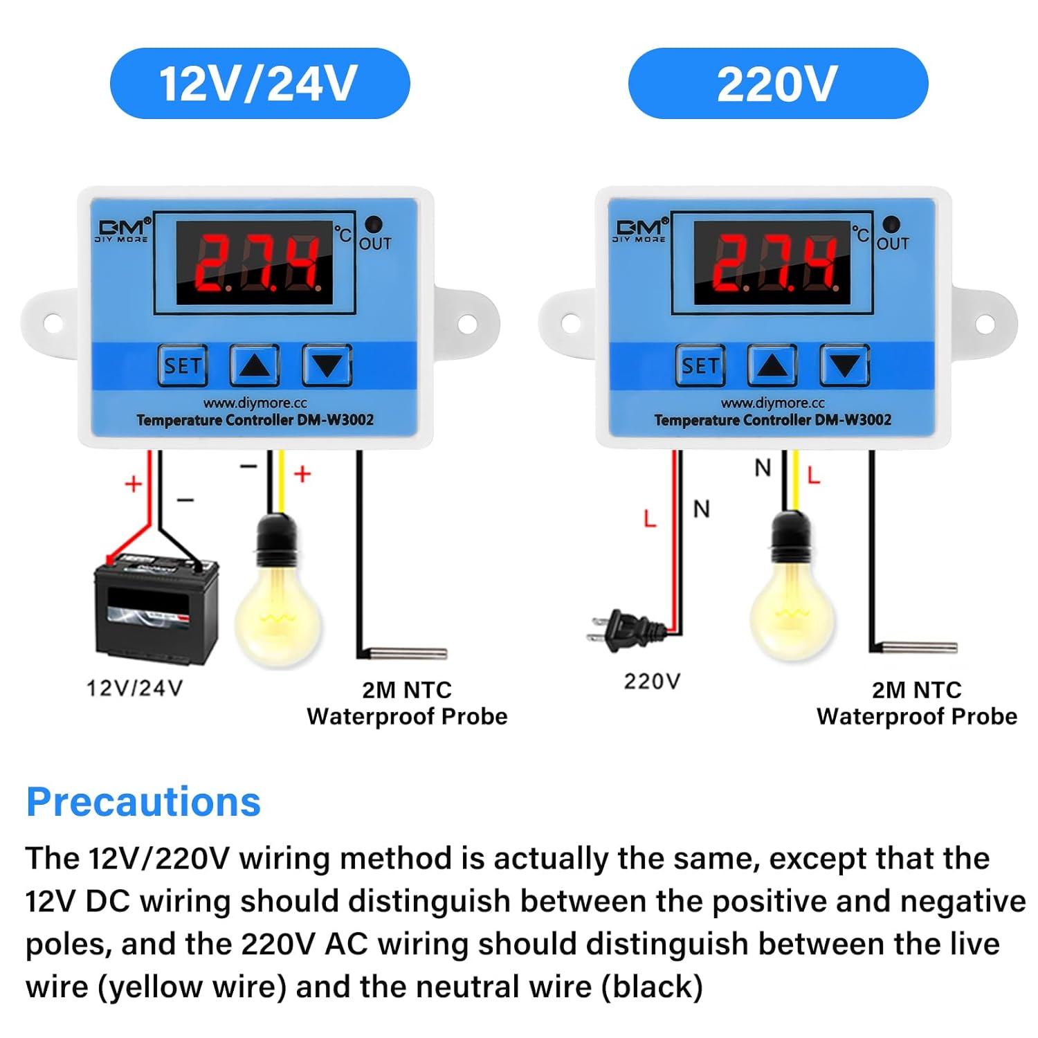
Figure 4: Wiring Diagram
This image displays wiring instructions for both 12V/24V DC and 220V AC versions of the W3002. For the AC 220V model, connect the live wire (L) to the input terminal and the neutral wire (N) to the other input terminal. The output terminals connect to your heating or cooling device, ensuring correct polarity for AC connections.
5.1. Wiring Steps (AC 110V-220V)
- Ensure the power supply is disconnected before wiring.
- Connect the AC 110V-220V power input to the designated input terminals on the controller. The yellow wire is typically Live (L) and the black wire is Neutral (N).
- Connect your heating or cooling device (load) to the output terminals of the controller.
- Insert the NTC10K waterproof temperature probe into the environment where temperature needs to be measured.
- Once all connections are secure, you can connect the power supply.
6. Operating Instructions
The W3002 controller is operated using the 'SET' button and the 'Up' and 'Down' arrow buttons.

Figure 5: Control Panel and Parameters
This diagram labels the components of the W3002 control panel, including the detection temperature display, output indicator, setting key, and up/down buttons. It also presents a table of control panel parameters (P0-P3) with their functions, setting ranges, and factory default values.
6.1. Basic Operation
- Upon powering on, the controller will display the current temperature measured by the probe.
- The 'OUT' indicator light will illuminate when the output is active (heating or cooling device is on).
6.2. Setting Parameters
To access and modify parameters:
- Press the 'SET' button for approximately 3 seconds to enter the parameter setting menu. The display will show 'P0'.
- Use the 'Up' and 'Down' buttons to navigate between parameters (P0, P1, P2, P3).
- Once the desired parameter is displayed, press 'SET' briefly to view its current value.
- Use the 'Up' and 'Down' buttons to adjust the value.
- Press 'SET' again to confirm the new value and exit the parameter setting, or wait a few seconds for it to automatically save and exit.
Parameter Descriptions:
- P0: Start Temperature
Sets the temperature at which the device will turn on. - P1: Stop Temperature
Sets the temperature at which the device will turn off. - P2: Temperature Calibration
Allows for fine-tuning the temperature reading if there is a discrepancy with a known accurate thermometer. Range: -10°C to 10°C. - P3: Start Delay
Sets a delay (in minutes) before the device starts operating after the temperature condition is met. This can protect compressors in cooling systems. Range: 0 to 10 minutes.
6.3. Heating and Cooling Modes
The W3002 automatically determines whether to operate in heating or cooling mode based on the relationship between P0 (Start Temperature) and P1 (Stop Temperature).

Figure 6: Heating and Cooling Mode Configuration
This image provides examples for configuring the W3002 for both heating and cooling applications. It shows that if the start temperature (P0) is less than the stop temperature (P1), the controller operates in heating mode. If P0 is greater than P1, it operates in cooling mode. Specific use cases for a water heater and an electrical cabinet cooler are detailed.
Heating Mode Configuration:
- Set P0 (Start Temperature) < P1 (Stop Temperature).
- Example: To heat to 50°C and reactivate heating at 40°C:
- Set P0 = 40°C
- Set P1 = 50°C
Cooling Mode Configuration:
- Set P0 (Start Temperature) > P1 (Stop Temperature).
- Example: To cool to 26°C and reactivate cooling at 30°C:
- Set P0 = 30°C
- Set P1 = 26°C
7. Troubleshooting
The W3002 controller can display error codes to indicate specific issues.

Figure 7: Error Codes and Factory Reset
This image illustrates the display for restoring factory settings ('888') and common error codes: 'LLL' for an open-circuit sensor fault and 'HHH' for a short-circuit sensor fault.
7.1. Error Codes
- LLL: Indicates an open-circuit sensor fault. The temperature probe may be disconnected or damaged. Repair or replace the probe.
- HHH: Indicates a short-circuit sensor fault. The temperature probe may be shorted or damaged. Repair or replace the probe.
7.2. Restoring Factory Settings
To restore the controller to its factory default settings:
- While powered on, press and hold both the 'Up' and 'Down' arrow buttons simultaneously for approximately 3 seconds.
- The display will show '888', indicating successful restoration of factory settings.
- The system will then automatically return to temperature detection mode.
8. Maintenance
- Keep the controller unit clean and free from dust. Use a dry, soft cloth for cleaning.
- Regularly inspect the wiring for any signs of damage or loose connections.
- Ensure the temperature probe is clean and free from debris that could affect its accuracy.
- Avoid exposing the controller to extreme temperatures or direct sunlight for prolonged periods.
9. Applications
The diymore W3002 Digital Temperature Controller is suitable for a wide range of applications where precise temperature control is required.

Figure 8: Typical Applications
This image displays various environments where the W3002 controller can be effectively used, including incubation rooms, aquariums, greenhouses, and livestock farming facilities.
10. Warranty and Support
For warranty information or technical support, please refer to the product packaging or contact diymore customer service directly through their official website or the platform where the product was purchased. Keep your purchase receipt for warranty claims.


