1. Product Overview
The ELING Mini Universal GPS Speedometer Signal Sensor Sender Adapter Kit is designed to provide a reliable and accurate speed signal for various speedometer and tachograph applications. This kit offers an easy installation process, eliminating the need for complex mechanical speed senders.
Key Features:
- Suitable for all types of speedometers and tachographs.
- High accuracy with only 0.2% deviation, significantly better than mechanical sensors (3-5% deviation).
- Features Anti-GPS Stationary Drift technology for consistent readings.
- Supports both Negative & Positive Pulse output with a maximum of 50,000 pulses/km.
- Compatible with various gauges, offering programmable speed ratio and starting at a low speed of 0.5 km/h.
- Outputs two reverse speed signals.
- Shockproof design with built-in circuit protection.
- Includes Pulse/Odometer Compensation for tunnels or under bridges.
- Equipped with a high-quality GPS Active Antenna for reliable performance in adverse weather conditions.
- Compact size: 4.5cm (L) x 1.9cm (W) for the sensor, with a 100cm extended cable.
- GPS Antenna cable length: 300cm.
- Working Voltage: DC12V/24V (6~36V DC).
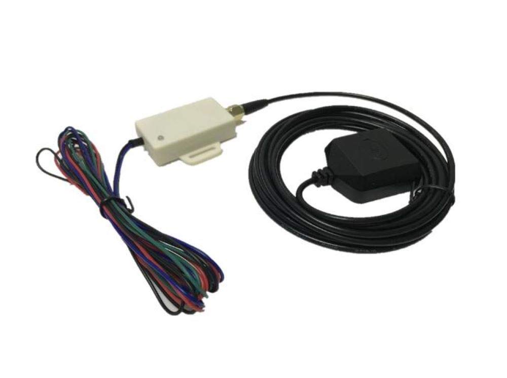
Figure 1.1: Overview of the ELING Mini Universal GPS Speedometer Signal Sensor Kit, showing the main sensor unit, wiring harness, and GPS antenna.

Figure 1.2: The compact GPS speed sensor unit alongside its active GPS antenna, ready for installation.
2. Setup and Wiring
This section details the wiring connections and initial setup for the GPS speed sensor.

Figure 2.1: Wiring diagram for the ELING GPS Speed Sensor, illustrating connections to the speedometer/tachograph and GPS antenna.
2.1 Cable Definition:
- RED: Power +, DC8~32V (Connect a resistor as shown in the image if necessary for specific applications).
- BLACK: GROUND.
- GREEN: Speed Pulse Signal Output +.
- BLUE: Speed Pulse Signal Output –.
Please connect either the GREEN or BLUE cable (one of the two) to your current speedometer/odometer/tachograph, depending on its input requirements.
2.2 GPS Antenna Installation:
Securely fasten the GPS antenna. For optimal signal reception, it is preferable to install the antenna outdoors or inside the front windshield, ensuring it has a clear view of the sky to pick up satellite signals.
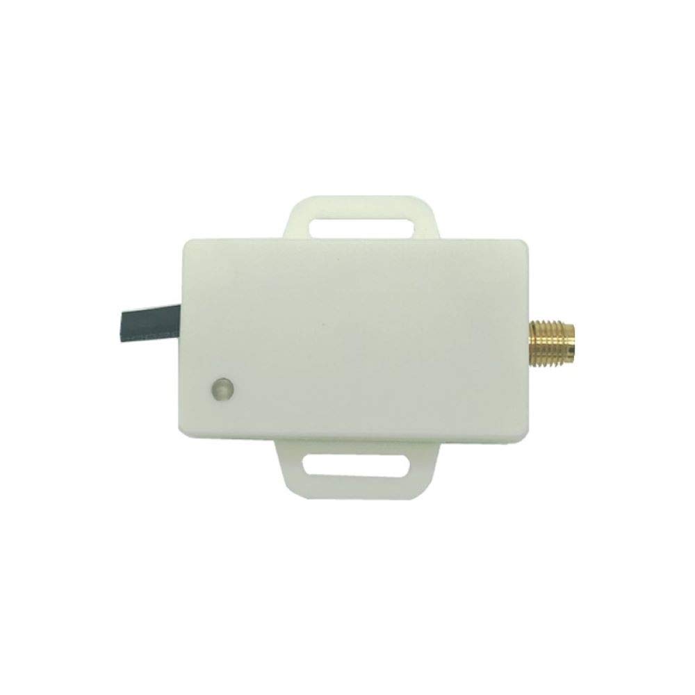
Figure 2.2: Top view of the GPS speed sensor unit, highlighting its compact design.

Figure 2.3: Bottom view of the GPS speed sensor, showing the 3M adhesive for secure mounting.
3. Operating Instructions: Programming Speed Ratio
The GS202 model allows for programming the speed ratio to accurately fit your specific speedometer or odometer/tachograph.

Figure 3.1: Visual guide for programming the speed ratio on the ELING GPS Speed Sensor.
- Connect Speed Signal: Connect the GREEN or BLUE cable from the sensor to your device (speedometer/odometer/tachograph).
- Power On: Apply power to the GS202 sensor and your speedometer.
- Initiate Programming: Press the button located via the hole on the sensor (refer to Figure 3.1 for location). Hold the button for 10 seconds. You will observe the speedometer needle start running, indicating entry into programming mode.
- Release Button: Release the button and wait for 5 seconds.
- Adjust Needle Direction: Hold the button again. The needle will run in the opposite direction.
- Set Speed Point: Use steps 3-5 repeatedly to make the speedometer needle point to 60 km/hr. Once the needle is at 60 km/hr, release the button, and then power off the unit.
- Setting Complete: The speed ratio setting is now complete.
The programmable speed ratio range for this device is 1~20,000 pulses per kilometer (ppk).
4. Specifications
| Feature | Detail |
|---|---|
| Model | GS202 (Programmable speed ratio) |
| Application | All kinds of Speedometer, Tachograph |
| Accuracy | 0.2% deviation (mechanical speed sensor typically 3-5% deviation) |
| Anti-GPS Stationary Drift | Yes |
| Pulse Output | Negative & Positive Pulse, Max 50,000 pulses/km |
| Speed Ratio Compatibility | Programmable, lowest 0.5km/h to start |
| Output Signals | Two reverse speed signals |
| Protection | Shockproof and Circuit Protection design |
| Odometer Compensation | When in Tunnel or under Bridge |
| Default Speed Ratio | 5000ppk (5000 pulses per km) |
| Sensor Dimensions | 4.5cm (L) x 1.9cm (W) |
| Sensor Cable Length | 100cm extended cable |
| GPS Antenna Cable Length | 300cm extended cable |
| Working Voltage | DC12V/24V Power Supply (6~36V DC) |
| Product Dimensions | 3.74 x 0.79 x 4.72 inches; 3.53 ounces |
| Material | Plastic |
| Manufacturer | ELING |
| ASIN | B0888JFHPK |
| UPC | 713721550944 |

Figure 4.1: Summary of technical specifications for the ELING Mini Universal GPS Speed Sender.
5. Troubleshooting
- Slow Initial GPS Fix: If the unit takes a long time (e.g., over a minute) to acquire a GPS signal upon startup, ensure the GPS antenna is installed in a location with a clear, unobstructed view of the sky. Avoid placing it under metal structures or inside enclosed spaces that block satellite signals.
- Inaccurate Speed Readings:
- Verify that the speed ratio programming (Section 3) has been performed correctly and matches the requirements of your speedometer.
- Check all wiring connections (Section 2.1) for proper contact and ensure no wires are loose or short-circuited.
- Ensure the GPS antenna is securely connected and not damaged.
- No Speed Signal Output:
- Confirm that the unit is receiving proper power (RED and BLACK wires).
- Check if the GREEN or BLUE signal output wire is correctly connected to your speedometer's input.
- Allow sufficient time for the GPS unit to acquire a satellite fix.
- Intermittent Signal Loss (Tunnel/Bridge): The unit features Pulse/Odometer Compensation for such scenarios. If issues persist, ensure the unit is correctly installed and has stable power.
6. Maintenance
The ELING Mini Universal GPS Speedometer Signal Sensor is designed for low maintenance. Follow these general guidelines to ensure longevity:
- Keep Clean: Periodically wipe the sensor unit and GPS antenna with a soft, dry cloth to remove dust and debris. Avoid using harsh chemicals or abrasive cleaners.
- Inspect Wiring: Regularly check the wiring connections for any signs of wear, corrosion, or damage. Ensure all connections remain secure.
- Antenna Placement: Ensure the GPS antenna remains securely mounted and its view of the sky is not obstructed by new installations or modifications to the vehicle.
- Environmental Protection: While designed to be robust, avoid exposing the unit to extreme temperatures or direct water immersion beyond its intended use.
7. Warranty and Support
Your ELING Mini Universal GPS Speedometer Signal Sensor Kit comes with:
- One Year Limited Warranty: This warranty covers defects in materials and workmanship under normal use for one year from the date of purchase.
- Free Lifetime Technical Support: For any questions regarding installation, operation, or troubleshooting, please contact ELING customer support.
For support, please refer to the contact information provided with your purchase or visit the official ELING website.


