Introduction
This document provides comprehensive instructions for assembling, operating, and maintaining the Icstation FM Radio Kit (Model GY18041). This kit is designed as an educational soldering project, suitable for individuals interested in electronics and developing soldering skills. Upon successful assembly, the kit functions as a compact FM radio receiver.
The kit includes all necessary electronic components and a printed circuit board (PCB) to construct a functional FM radio. It operates on a frequency range of 76MHz-108MHz and features low power consumption, a power failure memory function, and clear silk screen markings on the PCB for component placement.
Safety Information
No Warning Applicable.
While no specific warnings are provided, general safety precautions for electronic assembly and soldering should always be observed:
- Always work in a well-ventilated area when soldering.
- Wear appropriate eye protection to prevent solder splashes or fumes from entering the eyes.
- Use a soldering iron stand to prevent accidental burns.
- Ensure the soldering iron is unplugged and cooled before storing.
- Keep small components away from young children to prevent choking hazards.
- Handle electronic components carefully to avoid damage from static electricity.
What's in the Box
The Icstation FM Radio Kit includes the following components:
- Printed Circuit Board (PCB)
- Electronic Components (resistors, capacitors, inductors, integrated circuit, buttons, etc.)
- 3.5mm Headphone Jack
- Battery Holder (for 2x AA batteries)
- Cable Ties
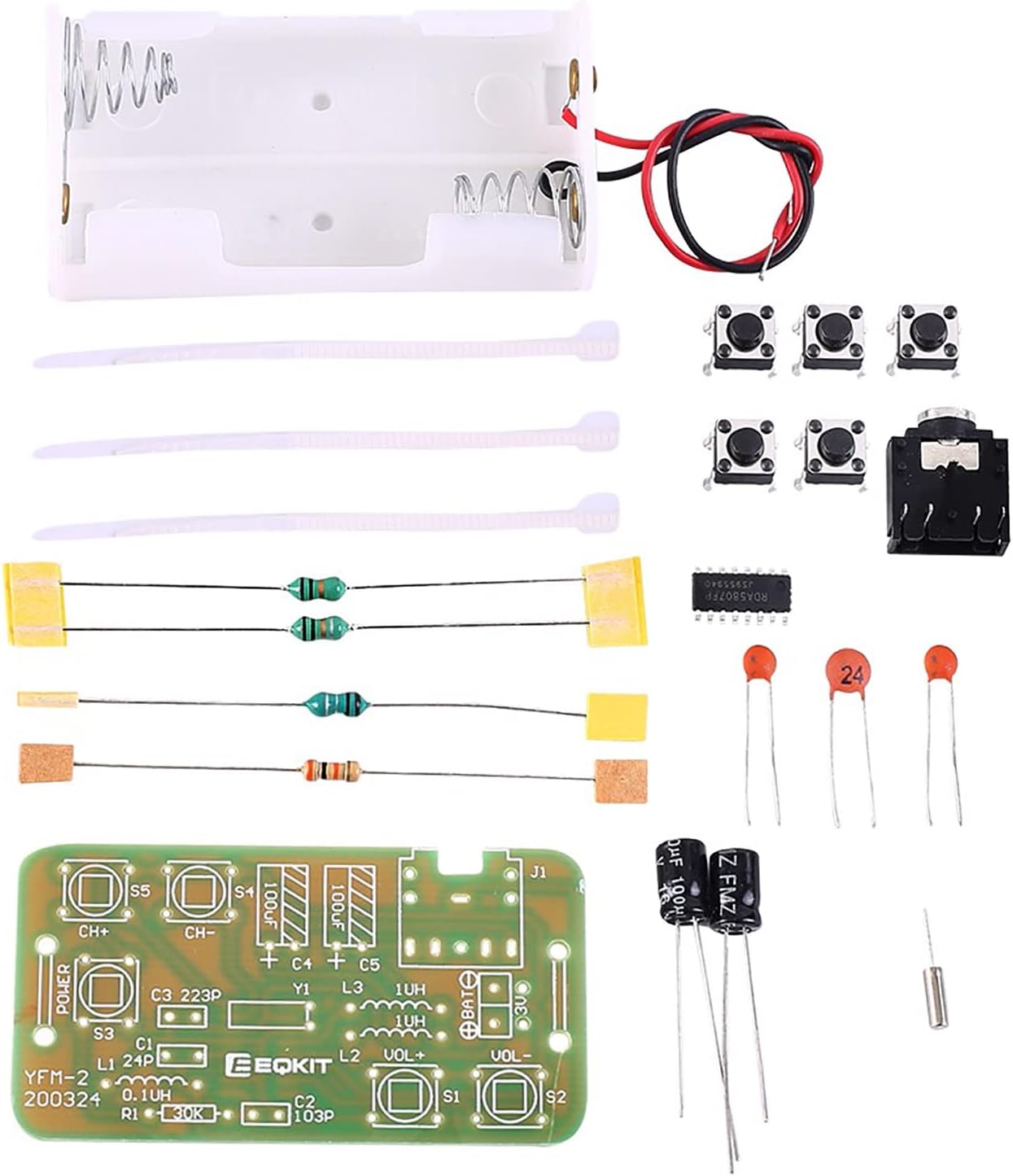
Figure 1: All components included in the DIY FM Radio Kit. This image displays the PCB, various resistors, capacitors, inductors, push buttons, the integrated circuit chip, a 3.5mm headphone jack, a battery holder, and cable ties.
Components Overview
Familiarize yourself with the main components and their placement on the Printed Circuit Board (PCB). The PCB features clear silk screen markings indicating component types and their correct orientation.

Figure 2: Top and bottom views of the Printed Circuit Board (PCB). The top side shows component outlines and labels, while the bottom side shows the solder pads and traces.
Key components and their functions:
- Integrated Circuit (IC): The main processing unit for FM reception. This is a surface mount device (SMD).
- Capacitors (C): Store electrical energy, used for filtering and tuning.
- Resistors (R): Limit current flow.
- Inductors (L): Store energy in a magnetic field, used for tuning and filtering. Note that some inductors may resemble resistors in appearance.
- Push Buttons (S1-S5): Used for power, channel selection, and volume control.
- 3.5mm Headphone Jack (J1): Output for audio.
- Battery Connection (BAT): Points for connecting the battery holder.

Figure 3: Assembled PCB highlighting the 3.5mm headset jack and channel switching buttons (CH+, CH-).

Figure 4: Assembled PCB highlighting the power button (S3) and volume adjustment buttons (VOL+, VOL-).
Assembly Instructions
This kit requires basic electronic knowledge and soldering skills. The PCB is clearly marked with component outlines and values to guide assembly. It is recommended to solder smaller components first, then larger ones.
- Prepare Your Workspace: Ensure a clean, well-lit, and well-ventilated area. Gather your soldering iron, solder, desoldering braid/pump, wire cutters, and safety glasses.
- Identify Components: Match each component from the kit to its corresponding marking on the PCB. Pay close attention to component values (e.g., resistor color codes, capacitor markings) and polarity for polarized components like electrolytic capacitors (marked with a '+' for the positive lead).
- Solder the Integrated Circuit (IC): The IC is a surface mount device (SMD). Carefully align the IC with the pads on the PCB. It is highly recommended to use soldering flux to prevent solder bridges between pins. Solder one corner pin first to secure the IC, then align the remaining pins and solder them. Inspect carefully for any short circuits between pins.
- Solder Resistors and Inductors: Insert resistors (R1) and inductors (L1, L2, L3) into their designated holes. Bend the leads slightly on the underside of the PCB to hold them in place, then solder and trim excess leads. Be aware that some inductors may look like resistors.
- Solder Capacitors: Insert ceramic capacitors (C1, C2, C3) and electrolytic capacitors (C4, C5). Ensure electrolytic capacitors are inserted with the correct polarity (the longer lead is usually positive, and the PCB will have a '+' marking). Solder and trim leads.
- Solder Push Buttons: Insert the five push buttons (S1, S2, S3, S4, S5) into their respective positions. They are typically non-polarized. Solder all pins securely.
- Solder 3.5mm Headphone Jack: Insert the headphone jack (J1) into its designated spot. Solder all connection points.
- Connect Battery Holder: Connect the red wire from the battery holder to the '+' terminal and the black wire to the '-' terminal on the PCB's battery connection points (BAT). Solder these connections firmly.
- Final Inspection: Visually inspect all solder joints for cold joints (dull, grainy appearance), solder bridges (solder connecting two points that should not be connected), and correct component placement/orientation. Clean any flux residue if necessary.

Figure 5: Example of a fully assembled FM Radio Kit.
Operating Instructions
Once assembled, the FM Radio Kit is ready for operation.
- Insert Batteries: Place two AA batteries into the battery holder, ensuring correct polarity.
- Connect Headphones: Plug a 3.5mm stereo headphone or earbud into the headphone jack (J1). The headphone cable also acts as the antenna.
- Power On: Press the POWER button (S3) to turn on the radio.
- Adjust Volume: Use the VOL+ (S1) and VOL- (S2) buttons to adjust the listening volume.
- Tune Channels: Use the CH+ (S5) and CH- (S4) buttons to scan for FM radio stations. Press and release the button, then wait briefly for the radio to lock onto a station.
- Power Off: Press the POWER button (S3) again to turn off the radio. The radio has a memory function that will recall the last tuned station and volume setting upon next power-on.
Maintenance
The Icstation FM Radio Kit requires minimal maintenance. Follow these guidelines to ensure longevity:
- Cleaning: Use a soft, dry cloth to wipe the PCB and components. Avoid using liquids or abrasive cleaners.
- Storage: Store the assembled radio in a dry, cool place away from direct sunlight and extreme temperatures.
- Battery Care: Remove batteries if the radio will not be used for an extended period to prevent leakage.
- Handle with Care: Avoid dropping or subjecting the radio to strong impacts, as this can damage solder joints or components.
Troubleshooting
If you encounter issues with your assembled FM Radio Kit, consider the following troubleshooting steps:
| Problem | Possible Cause | Solution |
|---|---|---|
| Radio does not power on. |
|
|
| No sound or very low sound. |
|
|
| Cannot tune to stations / Static. |
|
|
| Buttons not responding. |
|
|
Specifications
Technical specifications for the Icstation FM Radio Kit:
| Feature | Detail |
|---|---|
| Product Name | FM Radio DIY Soldering Kit |
| Work Voltage | DC 3V (2x AA batteries in series) |
| Working Current | Approximately 19mA |
| Receiving Frequency | 76MHz - 108MHz |
| Headphone Impedance | 32 Ω |
| PCB Size | 56.2mm x 30mm |
| Kit Weight | 13g |
| Product Dimensions (Assembled) | 1.5 x 1.2 x 0.75 inches (approx. 38 x 30 x 19 mm) |
| Item Model Number | GY18041 |
| Manufacturer Recommended Age | 15 years and up |

Figure 6: Assembled kit with key specifications.

Figure 7: Dimensional view of the assembled kit (approx. 32mm x 20mm x 57mm).
Warranty and Support
For specific warranty information regarding your Icstation FM Radio Kit, please refer to the documentation provided with your purchase or contact the seller directly. As this is a DIY soldering kit, successful operation is dependent on the assembler's skills and adherence to instructions.
For technical support or inquiries, please contact Icstation customer service through their official channels or the platform where the product was purchased.