
1. Introduction
This manual provides essential information for the safe and effective installation, operation, and maintenance of your DALY 4S 12V 100A LifePO4 Battery Management System (BMS) Protection Board. The DALY BMS is designed to optimize the performance and extend the lifespan of your lithium battery pack by providing crucial protection features. Please read this manual thoroughly before proceeding with any installation or operation.
2. Product Features
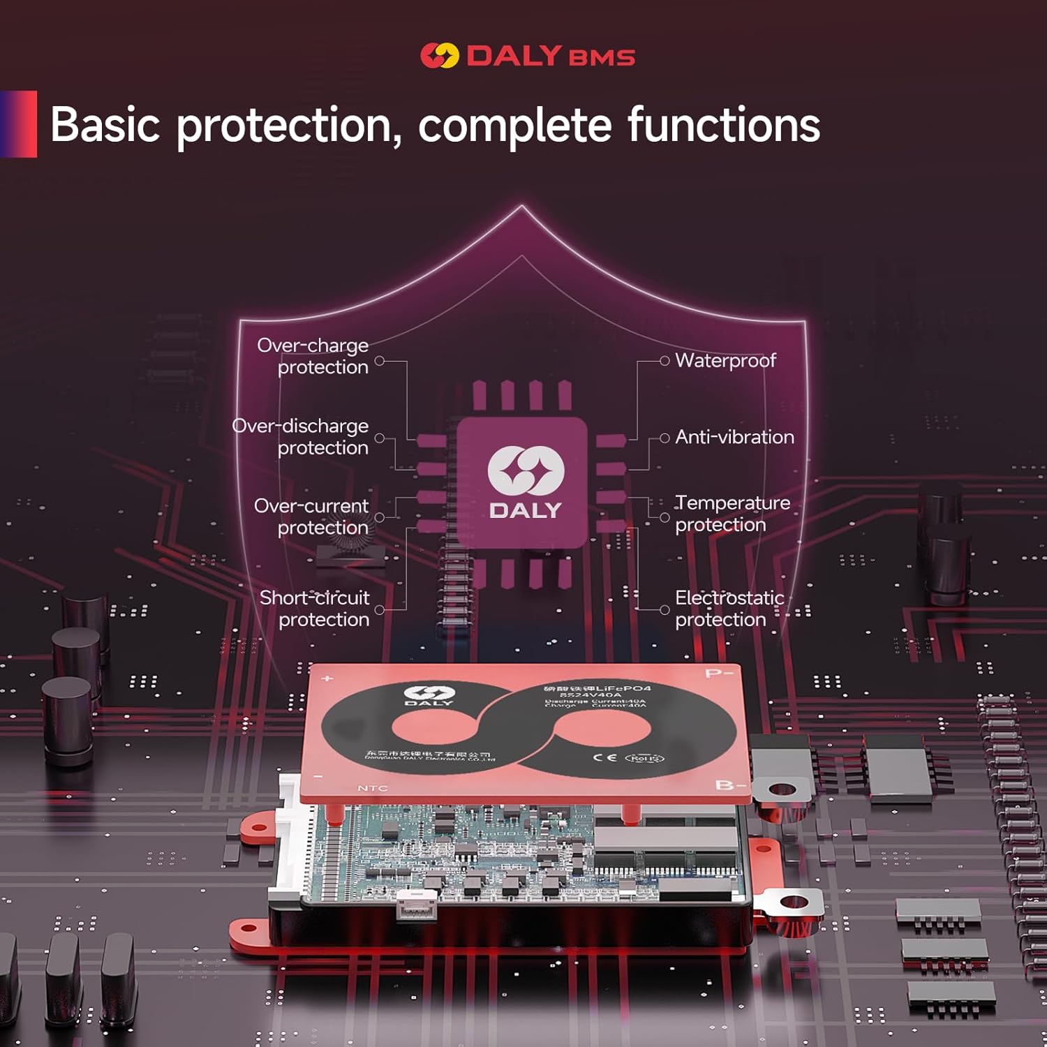
- Comprehensive Protection: Includes overcurrent, overcharge, overdischarge, short circuit, and temperature protection to safeguard your battery pack.
- Enhanced Durability: Features double protection through injection patent technology and a robust patent shell, making it waterproof, dustproof, shockproof, and anti-static.
- High-Quality Components: Constructed with high-quality components for reliable performance and high acquisition accuracy.
- Optimized Battery Performance: Maximizes and optimizes lithium battery performance, significantly extending battery lifetime.
- Easy Installation: Designed for straightforward plug-and-unplug connections, simplifying the electrical connection between the battery pack and the BMS.

3. Specifications
| Parameter | Value |
|---|---|
| Product Type | LifePO4 4S 100A BMS with Balance |
| Product Dimensions | 2.56 x 6.54 x 0.94 inches |
| Item Weight | 13.6 ounces (260±60g) |
| Voltage | 12 Volts |
| Input Voltage | 12 Volts |
| Discharge Current | 100A |
| Overdischarge Current | 266±20A |
| Charging Current | 100A |
| Overcharge Current | 106±20A |
| Overcharge Voltage | 3.75V±0.05V |
| Overdischarge Voltage | 2.2V±0.05V |
| Charge Voltage | 14.6V |
| Output Wire | 7AWG/100mm |
| Cable | 24AWG/300mm |

4. Package Contents
The DALY 4S 12V 100A LifePO4 BMS Protection Board package includes the following items:
- 3.2V LifePO4 BMS x1
- NTC Temperature Sensor x1
- Sampling Cable x1
- Instruction Manual x1
- B-P-Cable (Gift) x1

5. Safety Information
Always prioritize safety when working with battery management systems and lithium battery packs. Incorrect installation or handling can lead to serious damage to the BMS, battery, or personal injury.
- Ensure all connections are correct and secure before applying power.
- Do not insert the BMS connector into the battery pack until all balance wires are properly connected and verified.
- Avoid short circuits during wiring and installation.
- Use appropriate insulated tools when working with battery components.
- If you are unsure about any step, consult a qualified professional or contact DALY customer support.
6. Installation and Wiring
Proper installation and wiring are critical for the correct function and safety of your DALY BMS. Follow these steps carefully.
6.1 Common Wiring Errors to Avoid
Understanding common mistakes can prevent damage to your BMS and battery pack. Pay close attention to these points:
- Incorrect Wiring Use: Always use the wiring provided with your DALY BMS. Wires from different manufacturers may have slight differences that can lead to poor contact or socket shedding.
- Inserting BMS Before Wiring: Never insert the BMS connector into the battery pack before all balance wires are correctly welded to the battery. Doing so can cause internal components of the BMS to break down, leading to charging/discharging failures.
- Virtual Welding: Ensure all welds are solid and complete. Virtual welding (poor contact) can lead to leakage, increased burden pressure, and eventual damage to the battery or BMS.
- Lack of Pre-Inspection: Always inspect the battery pack wiring and verify the voltage of each string before inserting the BMS. Failure to do so can cause the BMS to burn out or damage sampling points.
- Incorrect P-line and B-line Connection: Ensure the P- line (total negative electrode of output/charging end) and B- line (total negative electrode of battery pack) are connected correctly. Incorrect connections can cause internal short circuits or burn out the protective plate.
6.2 Preparing Materials
Gather the necessary tools and components before starting the wiring process:
- DALY BMS Protection Board
- Balance Wires (Sampling Cable)
- NTC Temperature Sensor
- Lithium Battery Pack
- Multimeter (for voltage verification)
- Ceramic Scissors (insulated, for cutting wires)
- Soldering Iron and Solder Wire
- Double-sided tape (for securing wires)
6.3 Determining Sampling Points
Accurately identifying the sampling points on your battery pack is crucial for correct balance wire connection. Use a multimeter to verify each point.
- Identify the total negative electrode of the battery pack and mark it as B-. This will be your first sampling point.
- Identify the connection point between the second negative and the first positive electrode. Mark this as B1.
- Continue this process for all subsequent cells, marking each connection point (e.g., B2, B3, etc.) up to the total positive electrode, which will be B+.
- Use a multimeter set to DC voltage to verify the voltage at each sampling point. The voltage should increase incrementally by approximately 3V (for LifePO4 cells) as you move from B- towards B+.
6.4 Connecting the Balance Wires
Once the sampling points are determined and verified, proceed with connecting the balance wires:
- Secure the BMS to the battery pack using double-sided tape in an appropriate position.
- Identify the black wire in the sampling cable set. This is the B- wire. Connect it to the total negative terminal of the battery pack (B0).
- Connect the first red wire (B1) to the positive terminal of the first battery string.
- Continue connecting the red wires sequentially (B2, B3, etc.) to the positive terminals of each subsequent battery string.
- The last red wire will connect to the total positive electrode of the battery pack (B+).
- Ensure all connections are soldered securely.
- After all balance wires are connected to the battery pack, carefully insert the sampling cable connector into the BMS.
- Verify the voltage between adjacent cables starting from the header to ensure there are no wrong connections or missing connections.

7. Operation
Once correctly installed, the DALY BMS will automatically manage your LifePO4 battery pack. It continuously monitors cell voltages, currents, and temperatures to ensure safe charging and discharging within specified limits. The BMS will intervene by cutting off charge or discharge if any parameter exceeds safe thresholds, protecting the battery from damage.
8. Maintenance
To ensure the longevity and optimal performance of your DALY BMS and battery pack, consider the following maintenance tips:
- Keep the BMS and battery pack clean and free from dust and debris.
- Regularly inspect all wiring and connections for any signs of wear, corrosion, or looseness.
- Avoid exposing the BMS to extreme temperatures or direct sunlight for prolonged periods.
- Ensure adequate ventilation around the BMS, especially during high current operations.
9. Troubleshooting
If you encounter issues with your DALY BMS, consider the following basic troubleshooting steps:
- No Charge/Discharge: Verify all main power connections (P- and B-) and ensure the sampling cable is fully inserted and all balance wires are correctly connected to the battery. Check individual cell voltages with a multimeter.
- Overheating: Ensure the BMS has adequate ventilation and is not operating beyond its specified current limits.
- Unusual Readings: Recheck all balance wire connections and ensure they are secure and free from corrosion. Verify the multimeter is functioning correctly.
For more complex issues, refer to the detailed troubleshooting section in the full instruction manual or contact DALY customer support.
10. Warranty and Support
The DALY 4S 12V 100A LifePO4 BMS Protection Board is manufactured under strict quality control and is ISO/FCC/RoHS/PSE/CE APPROVED, ensuring a quality guarantee.
DALY offers 24-hour one-on-one customer service and lifetime technical support. For any inquiries, technical assistance, or warranty claims, please contact DALY customer support through the official channels provided at the point of purchase or on the manufacturer's website.
