1. Product Overview
The DALY BMS (Battery Management System) 4S 12V 60A LiFePO4 module is designed to protect 4-series (4S) Lithium Iron Phosphate (LiFePO4) battery packs. It ensures the safe and efficient operation of your battery system by providing essential protection functions and balancing capabilities. This standard BMS is suitable for various applications, including home energy storage and inverter systems.
Key Features:
- Comprehensive Protection: Includes overcurrent, overcharge, overdischarge, short circuit, and temperature protection to safeguard the battery pack.
- Cell Balancing: Helps to equalize the voltage across individual cells in the battery pack, extending battery life and improving performance.
- Robust Design: Features double protection through injection patent technology and a patent shell, offering waterproof, dustproof, shockproof, and anti-static properties.
- High-Quality Components: Constructed with pressure-resistant and durable materials, ensuring high acquisition accuracy and reliability.
- Easy Installation: Designed for straightforward connection to your battery pack.

Image 1.1: DALY BMS 4S 12V 60A LiFePO4 Battery Protection Module with included balance leads and NTC sensor.
2. Package Contents
Verify that all items are present in the package before proceeding with installation.
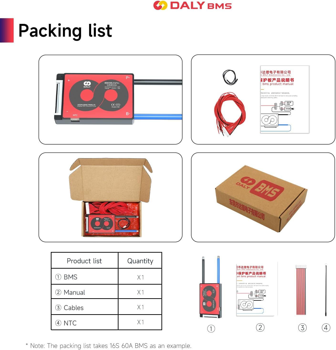
Image 2.1: Contents of the DALY BMS package, including the BMS unit, sampling cable, NTC sensor, and instruction manual.
| Item | Description | Quantity |
|---|---|---|
| BMS Unit | DALY 4S 12V 60A LiFePO4 Battery Protection Module | 1 |
| Sampling Cable | Balance leads for cell voltage monitoring | 1 |
| NTC Sensor | Temperature sensor | 1 |
| Instruction Manual | This document | 1 |
3. Safety Information
Please read and understand all safety instructions before installing or operating the DALY BMS. Failure to follow these instructions may result in electric shock, fire, serious injury, or property damage.
- Always disconnect the battery pack from any power sources before working on the BMS or battery connections.
- Ensure correct polarity when connecting the BMS to the battery pack. Incorrect wiring can damage the BMS and the battery.
- Wear appropriate personal protective equipment (PPE), including insulated gloves and eye protection, when handling batteries and electrical components.
- Do not short-circuit the battery terminals or the BMS output.
- Install the BMS in a well-ventilated area, away from flammable materials.
- This BMS is designed for LiFePO4 batteries only. Do not use it with other battery chemistries.
- If you are unsure about any part of the installation or operation, consult a qualified electrician or contact DALY customer support.
4. Installation and Wiring
Proper installation and wiring are crucial for the safe and effective operation of the BMS. Refer to the wiring diagram below and follow the steps carefully.

Image 4.1: Wiring diagram for the DALY H series 60A BMS, illustrating connections for the battery pack, sampling cable, and output wires.
Wiring Steps:
- Connect Sampling Cables:
- The first black cable in the sampling cable set connects to the negative terminal (B-) of the overall battery pack.
- The second red cable connects to the positive terminal of the first battery cell (B1+).
- The third red cable connects to the positive terminal of the second battery cell (B2+).
- Continue this pattern until all balance cables are connected to their respective cell positive terminals.
- Ensure the sampling cable connector is securely plugged into the BMS.
- Connect Output Wires:
- Connect the B- wire from the BMS to the overall negative electrode of the battery pack.
- Connect the P- wire from the BMS to the negative terminal of your load (e.g., inverter, electric machine).
- Connect the P+ wire from the BMS to the positive terminal of your load and charger.
- Verify Connections: After connecting all cables, use a multimeter to measure the voltage between adjacent cells starting from the header. Ensure there are no incorrect connections or missing connections.
- Activate BMS: After activating the BMS (typically by connecting the main battery terminals and then the balance leads), measure the voltage between P+ and P-. This voltage should be consistent with the overall battery pack voltage.
Important: Always connect the balance leads to the battery cells before connecting the main B- and P- wires to the BMS. Disconnect in reverse order: main B- and P- first, then balance leads.
5. Operating Principles
The DALY BMS continuously monitors the battery pack to ensure its safe and optimal performance. It provides several layers of protection:
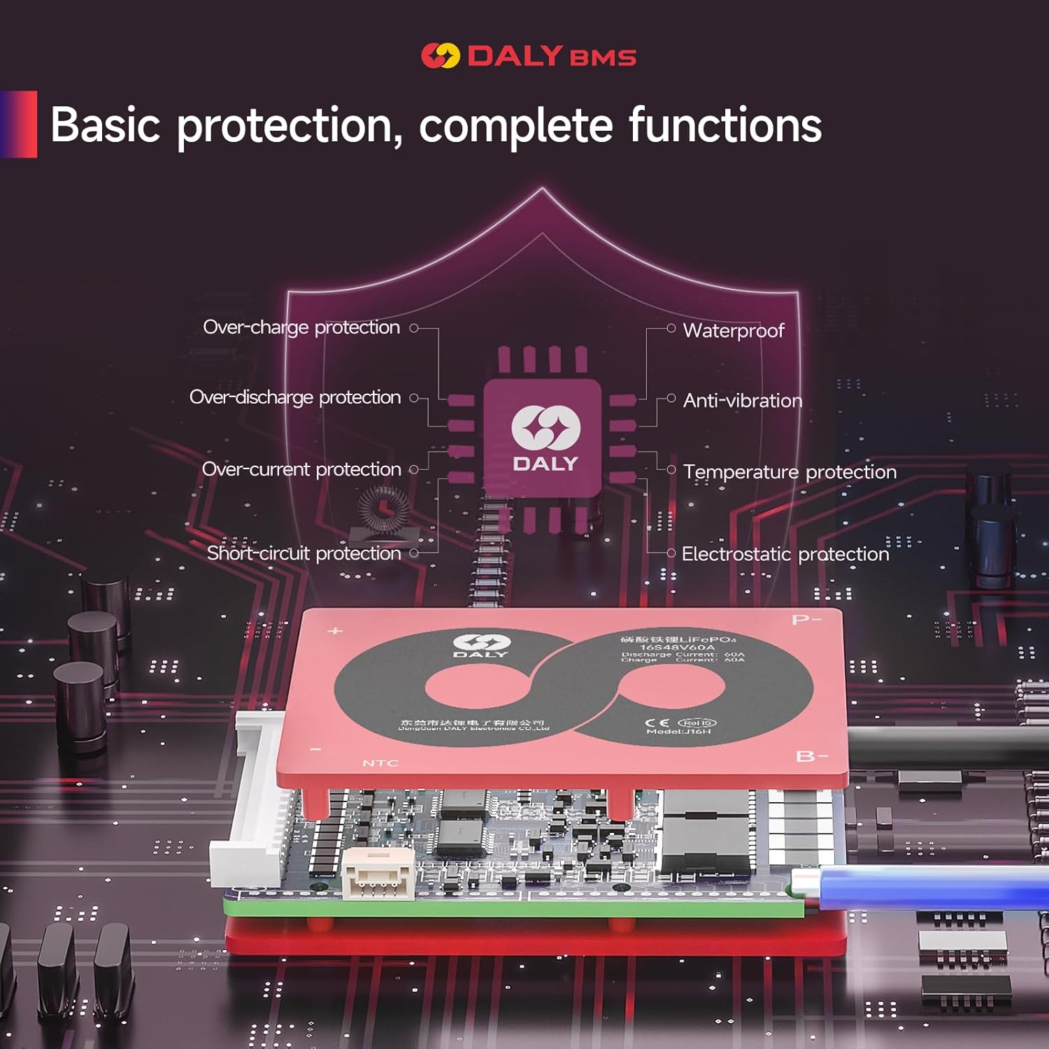
Image 5.1: Diagram illustrating the basic protection functions of the DALY BMS, including over-charge, over-discharge, over-current, short-circuit, temperature, anti-vibration, waterproof, and electrostatic protection.
- Over-charge Protection: Prevents individual cells from being charged beyond their safe voltage limit, which can lead to degradation or damage.
- Over-discharge Protection: Disconnects the load when cell voltages drop below a safe minimum, preventing irreversible damage to the cells.
- Over-current Protection: Limits the current drawn from or supplied to the battery to prevent overheating and damage to the cells or BMS.
- Short-circuit Protection: Immediately cuts off power in the event of a short circuit to prevent severe damage and fire hazards.
- Temperature Protection: Monitors the battery temperature and disconnects if it exceeds safe operating limits during charging or discharging.
- Cell Balancing: During charging, the BMS actively or passively balances the voltage of each cell to ensure they are all at a similar state of charge, maximizing the overall battery pack's capacity and lifespan.
The BMS operates automatically once correctly installed. It will trigger protection mechanisms as needed and resume normal operation once conditions return to safe parameters (e.g., after a short circuit is removed or temperature normalizes).
6. Maintenance
The DALY BMS is designed for minimal maintenance. However, periodic checks can help ensure long-term reliability:
- Visual Inspection: Periodically inspect the BMS and all wiring for any signs of damage, corrosion, or loose connections.
- Cleanliness: Keep the BMS free from dust and debris. Use a soft, dry cloth for cleaning. Do not use liquids or solvents.
- Environmental Conditions: Ensure the BMS operates within its specified temperature and humidity ranges to prevent premature failure.
- Battery Health: Monitor the overall health of your battery pack. While the BMS provides protection, it cannot compensate for severely degraded cells.
7. Troubleshooting
If you encounter issues with your DALY BMS, consider the following troubleshooting steps:
- No Output Voltage:
- Check all wiring connections, especially the main B- and P- terminals, and the balance leads. Ensure they are secure and correctly polarized.
- Verify that the battery pack voltage is within the normal operating range. An over-discharge protection might be active if the voltage is too low.
- Check for a short circuit on the output. The BMS will cut off output in such cases.
- Ensure the BMS has been properly activated after initial connection.
- Battery Not Charging:
- Confirm the charger is functioning correctly and connected to the P+ and P- terminals.
- Check if any cells are overcharged, triggering over-charge protection.
- Verify the NTC temperature sensor is correctly installed and the battery temperature is within the charging range.
- Unbalanced Cell Voltages:
- Ensure all balance leads are securely connected to their respective cell terminals.
- Allow sufficient time for the balancing function to work, especially during the top-off charge phase.
- Note that standard BMS units have passive balancing, which is slower than active balancing.
- BMS Overheating:
- Reduce the load current to ensure it does not exceed the BMS's continuous discharge current rating (60A).
- Ensure adequate ventilation around the BMS.
If the problem persists after performing these checks, contact DALY customer support for further assistance.
8. Specifications
The following table details the technical specifications for the DALY BMS 4S 12V 60A LiFePO4 module.
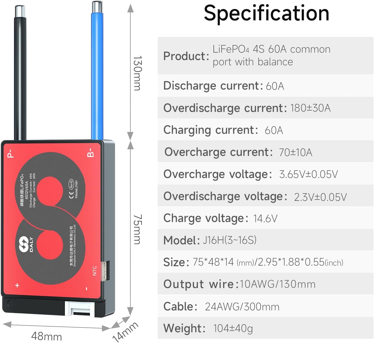
Image 8.1: Detailed specifications for the DALY LiFePO4 4S 60A common port BMS with balance.
| Parameter | Value |
|---|---|
| Product Type | LiFePO4 4S 60A common port with balance |
| Discharge Current | 60A |
| Overdischarge Current | 180±30A |
| Charging Current | 60A |
| Overcharge Current | 70±10A |
| Overcharge Voltage | 3.65V±0.05V |
| Overdischarge Voltage | 2.3V±0.05V |
| Charge Voltage | 14.6V |
| Model | J16H(3~16S) |
| Size (L×W×H) | 75×48×14 mm (2.95×1.88×0.55 inches) |
| Output Wire | 10AWG/130mm |
| Cable | 24AWG/300mm |
| Weight | 104±40g |
| Product Dimensions | 2.4 x 3.15 x 0.63 inches |
| Item Weight | 5.5 ounces (157 Grams) |
| Input Voltage | 12 Volts |
Additional Product Parameters (General for LiFePO4 4S BMS):

Image 8.2: Table showing various discharge, inner resistance, and charge parameters for LiFePO4 4S BMS across different current ratings.

Image 8.3: Table detailing overcharge protection, balance, overdischarge protection, over current protection, short circuit protection, and temperature protection parameters for LiFePO4 4S BMS.
9. Warranty and Support
Warranty Information:
DALY products are manufactured to high-quality standards. For specific warranty terms and conditions, please refer to the warranty card included with your product or visit the official DALY website. Keep your purchase receipt as proof of purchase for warranty claims.
Customer Support:
If you have any questions, require technical assistance, or need to report an issue, please contact DALY customer service. Contact details can typically be found on the official DALY website or through your point of purchase. Please have your product model number (707338961675) and purchase information ready when contacting support.
DALY offers 24-hour one-on-one customer service and lifetime technical support.


